953.026UK User Manual
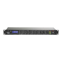
Front panel
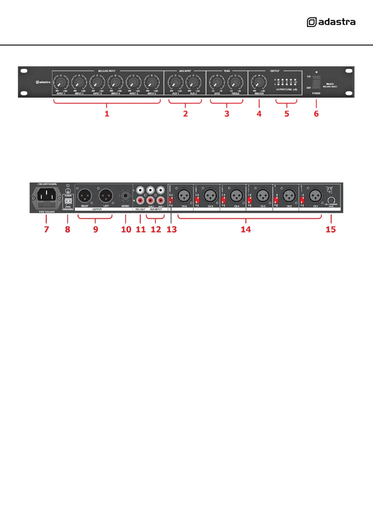
Rear panel
Connection
Ensure the Power (6) is switched off until all input and output connections are in place.
Turn all rotary level controls (1,2,4) fully down (anti-clockwise) to avoid loud noises when switching on.
Set the BASS and TREBLE Tone controls (3) to the vertical position (zero)
Connect microphones to the balanced XLR inputs on the rear panel (14).
For microphone inputs, set the Mic/Line DIP switch (13) to “MIC”
Where condenser microphones are used which require phantom power, set the PHANTOM DIP switch to “ON”
Alternatively, mono line inputs can be connected to any of the XLR inputs by setting this DIP switch to “LINE”
Stereo line level sources can be connected to AUX1 and AUX2 RCA inputs (12)
A recording output is provided on 2 RCA connectors (11), which is not governed by the MASTER level (4)
This can be connected to recording equipment or be used as an additional main output if required.
Main output is available via left and right balanced XLR sockets (9) and mono unbalanced 6.3mm jack (10)
Use any or all of these outputs to connect to the amplifier(s) or active speakers as required for the system.
Connect the rear IEC inlet (7) to the mains using the supplied mains lead (or an equivalent approved type).
Ensure that the supply voltage is correct for this equipment and that the mains outlet is switched on.
For mobile operation or away from mains supply, a 24Vdc input is provided on screw terminals (8).
Make sure the power switch is turned off before connecting to a 24Vdc power source and observe correct
polarity before powering up the unit on DC power.
 Loading...