10
ELECTRICAL CONNECTIONS
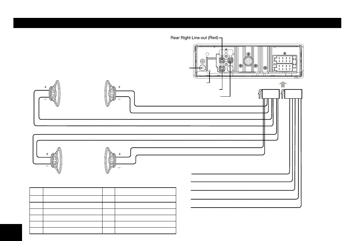
Wiring Diagram
Location
Function
Location
Function
F1 ront Right (-) / Gray with Black Stripe7
Ground / Black
2
Front Right (+) / Gray
8
3
Rear Right (-) / Purple with Black Stripe
9
Battery 12V(+) / Yellow
4 Rear Right (+) / Purple 10
15 1
16 2
Rear Left (-) / Green with Black Stripe
ACC+ / Red
Illumination / Brown
Rear Left (+) / Green
Blue Wire - AMP/ANT Remote (+12 Volt Out)
Black Wire - Ground
Brown Wire - Illumination Input (+)
Yellow Wire - Battery 12V(+)
Red Wire - ACC+
Front Left
Speaker
White Wire
White/Black Wire
Green/Black Wire
Green Wire
Gray Wire
Gray/Black Wire
Purple Wire
Purple/Black Wire
Front Right
Speaker
Rear Left Speaker Rear Right Speaker
Front Left(-) / White with Black Stripe
Front Left(+) / White
SUB OUT(Green)
BT Mic Port
ANTENNA
Rear Left Line-out (White)
11
INSTALLATION GUIDE
Installation Opening
This unit can be installed in any dashboard
having an opening as shown below. The
dashboard should be 4.75mm - 5.56mm thick
in order to be able to support the unit.
If the opening is too small, carefully cut or
183mm (7 3/16”)
52mm (2”)
as necessary until the sleeve easily slides into
the opening. Do not force the sleeve into the
opening or cause it to bend or bow. Check for
space behind the dashboard for the
unit chassis.
Reset
Press the RESET button with a ball point pen
to reset the unit to the original status.
Note: Press the RESET button will erase the
clock setting and stored stations.
Installation Procedures
m e t sys o i dua r eh t o yna evom e r , t nave l e r f I . 1
from the car.
2. Insert the mounting sleeve into the
dashboard. Fix it
in place by folding
down the metal tabs.
3.
4.
5.
P e r f o r m t h e required elec t r ica l
connections.
Then check that everything works before
installing the main unit.
Remove the two screws on the top of the
unit, otherwise, the CD will not work.
gn i su d r aobhsad eh t n i o i da r r ac eh t l l a t sn I . 6
the supplied screws (M5x6mm).
7. Attach the outer trim frame.
fI y o u are not sure how to install this unit
correctly, contact a
technician.
Mounting sleeve
Main unit
Trim plate
Remove the
two screws
Mounting bolt
Rubber cushion
ANTI-THEFT SYSTEM
This unit is equipped with a detachable panel.
Removing this panel makes the radio totally
inoperable.
Remove the detachable panel
sse rP . 1 button.
2. Hold the part popped out
and pull the panel out.
G .3 ently press the button
of the case and open the
cover. Place the panel
into the case and take it
with you when you leave
the car.
Install detachable panel
F .1 i x right part of face
plate in the panel slot of
the unit.
ed i s t f e l eh t nwod sse rP . 2
of the face plate until it
clicks into the panel slot.
Remove the unit
. t inu eht fo rewop eht f fo hct iw S .1
2. Remove the panel and
the trim plate.
I .3 nsert both Removal
Keys into the hole on the
front of the set until they
lock.
4. Pull out the unit.
2