L-854 Radio Control Equipment
96A0390 Rev.J
DISCLAIMER / WARRANTY
© ADB Airfield Solutions All Rights Reserved12
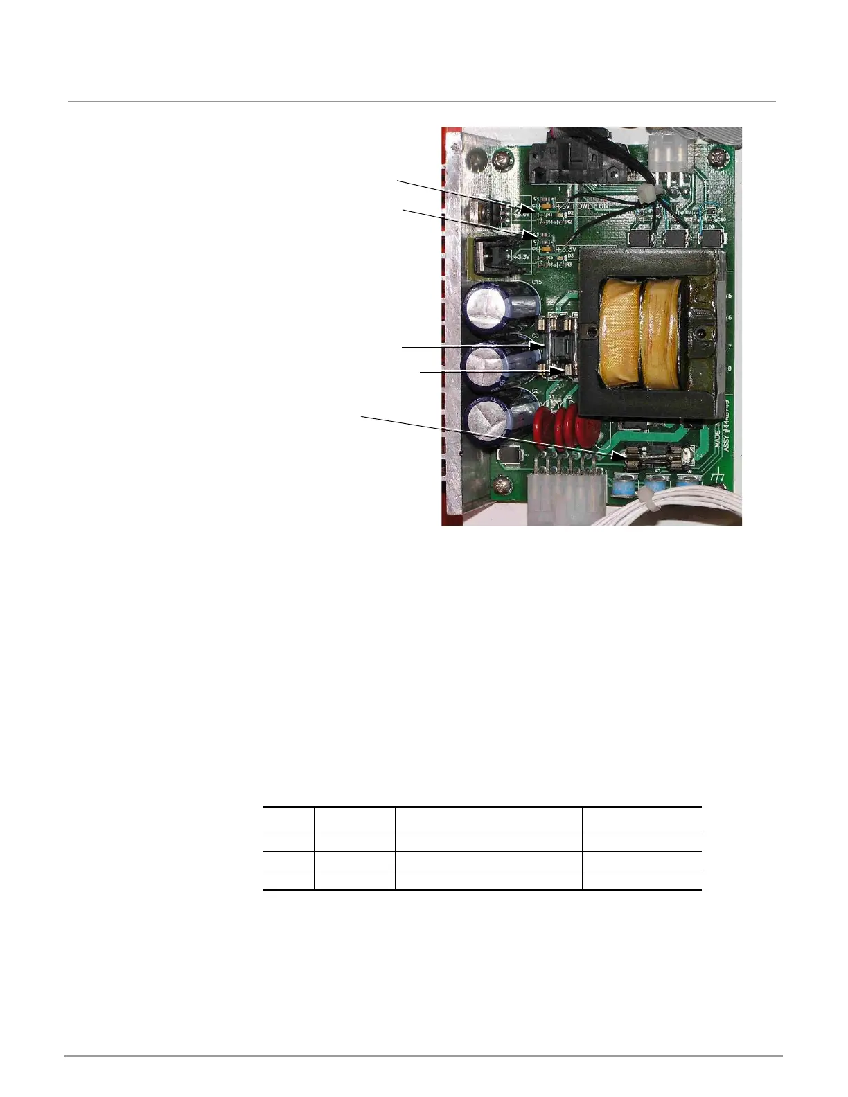
2.2.7.4 Power Supply Board Figure 4: Power Supply Board 44A6747
See Figure 4. The Power Supply board provides 5 VDC and 3.3 VDC to the various boards in
the system. Input power is brought in through the (see Table 4), Terminal Block at the bottom
of the cabinet. Input power options include:
• 120 VAC ±10% 50/60 Hz
• 240 VAC ±10% 50/60 Hz
• 12 VDC ±20%
• 48 VDC ±20%
Note that the correct wiring harness is included when the unit is shipped from the factory; it is
not possible to change the input voltage in the field.
There are two status LEDs on the board. The top LED shows that 5V power is available, and
the lower LED shows that 3.3V power is available. The Control Board also monitors the DC
voltage output, and will issue an alarm to the display if the voltages are out of specification.
See “Troubleshooting” on page 22.
There are three fuses on the board, as shown below in Table 5.
Table 5: Power Supply Fuse Layout
ITEM PART DESCRIPTION FUNCTION
F1 47A0213 .5A 5mm x 20mm SLO BLO 240 VAC Input
F2 47A0213 .5A 5mm x 20mm SLO BLO 120V VAC Input
F3 47A0214 5A 5mm x 20mm SLO BLO DC Input
5V DC Status LED
3.3V DC Status
LED
F1 – 240V AC Input
Fuse 47A0213
F2 – 120V AC Input
Fuse 47A0213
F3 – DC Input Fuse
47A0214
 Loading...