L-854 Radio Control Equipment
96A0390 Rev.J
DISCLAIMER / WARRANTY
© ADB Airfield Solutions All Rights Reserved14
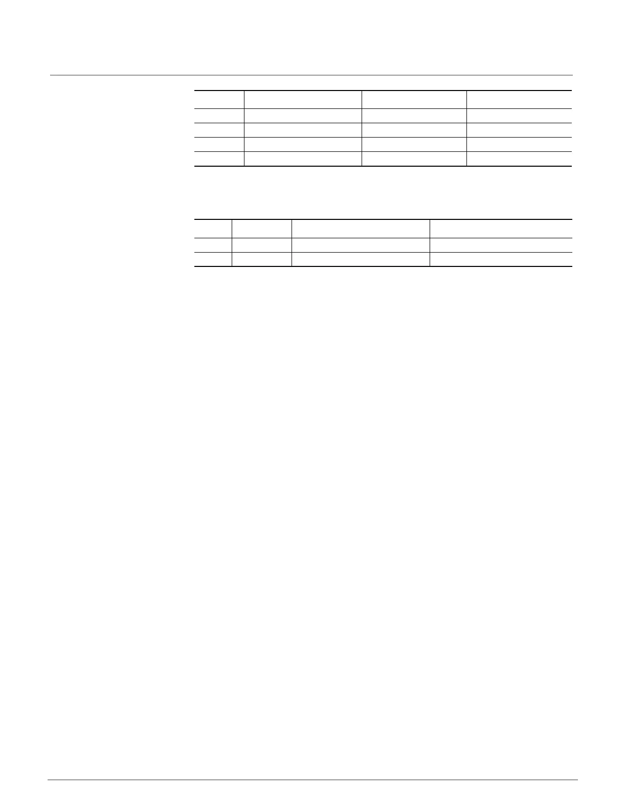
Table 8: Radio Control Configuration Switch
A set of LEDs above each solid state relay shows that relay’s commanded status.
There are two fuses on the board, as shown below in Table 9.
Table 9: Relay Board Fuse Layout
POSITION DESCRIPTION ON OFF
4 Debug Mode Do Not Use Debug Mode Off
3 Canada Mode J Operation Canada Mode J Standard Operation
2 Relay Channel A Operation Cumulative Mode Individual Mode
1 Relay Channel B Operation Cumulative Mode Individual Mode
ITEM PART DESCRIPTION FUNCTION
F1 47A0214 5A 5mm x 20mm SLO BLO Ch A Switch Voltage Input
F2 47A0214 5A 5mm x 20mm SLO BLO Ch B Switch Voltage Input
 Loading...