ADCP-61-471 • Issue 4 • June 2000 • Section 2: Operation and Maintenance
2-218
© 2000, ADC Telecommunications, Inc.
DLP-570
Page 8 of 18
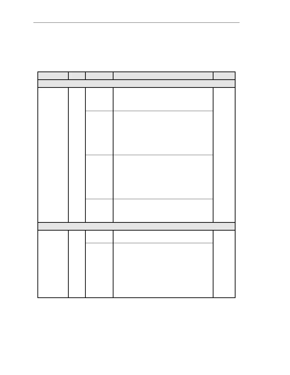
Table 570-1. RTAU Configuration Fields, continued
FIELD TYPE OPTIONS DESCRIPTION DEFAULT
EQUIPMENT SETUP FIELDS, continued
Mode,
continued
Toggle SPLTFL SPLTFL indicates a split in both the A and B paths and
connects an SPD to the line incoming from the F direction
and a TSG to the line outgoing in the F direction similar to
SPLTF mode. The signal in the E direction is looped back.
LOOPE The LOOPE mode is a full split of both A and B
transmissions paths. The incoming line in the E direction is
connected to the SPD and this line is connected to the
outgoing line in the E direction. The circuit will be looped in
one direction. The outgoing line in the F direction (non-test
direction) will be connected to a QRSS source and the line
incoming from the F direction is terminated by the nominal
characteristic impedance of the line.
LOOPF The LOOPF mode is a full split of both A and B
transmissions paths. The incoming line in the F direction is
connected to the SPD and this line is connected to the
outgoing line in the F direction. The circuit will be looped in
one direction. The outgoing line in the E direction (non-test
direction) will be connected to a QRSS source and the line
incoming from the E direction is terminated by the nominal
characteristic impedance of the line.
DISABLE When DISABLE is selected, no monitor or split access can
take place. Setting the Mode field to DISABLE also stops
any measurement in progress, as if the Measurement field
(described below) had been set to STOP.
SIGNAL GENERATOR SETUP FIELDS
Pattern Type Toggle OVERVIEW: If the desired pattern type is not available,
select the User Code option to enter a pattern 32 bits or less.
QRS
QRS Quasi-Random Signal. QRS (2
20
-1) is a 1,048,575-bit
sequence generated by a 20-stage shift register with feedback
taken from the 17th and 20th stages. The non-inverted output
is taken from the 20th stage, and an output bit is forced to be
a ‘1’ whenever the next 14 bits are all 0’s. QRS is typically
used to verify continuity and to check circuit performance in
the presence of traffic-like signals. QRS (Quasi-random
Signal) is a signal repeated every 1 to 24 bits as specified by
the OS (Operation System) application. QRS must conform
to the description in Bellcore TR-NPL-000054.
(continued)