ADCP-61-471 • Issue 4 • June 2000 • Section 2: Operation and Maintenance
2-28
© 2000, ADC Telecommunications, Inc.
DLP-501
Page 1 of 2
CHASSIS INSPECTION
Summary:
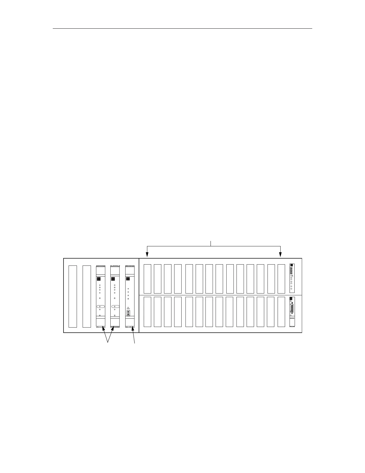
This procedure provides instructions for identifying the Soneplex Broadband chassis
and module locations. The chassis front and locations for modules are shown in Figure 501-1.
The chassis backplane is shown in Figure 501-2.
1. See Figure 501-1 to identify module locations at the front of the chassis. A working DS3
MUX module, an APU, and an MPU are always required. The slots identified for low-
speed modules can house:
• Up to 14 ODS2 modules (7 working and 7 protect),
• 28 HLXC modules,
• 28 DLX modules,
• 28 RLX modules, or
• Any combination up to a maximum of 28 DS1 circuits.
2. See Figure 501-2 to identify components and locations on the chassis backplane.
Stop! You have completed this procedure.
5915-B
RTAU
MODULE
LOW SPEED UNITS
HSW
HSP
TAU
APU
MPU
MXPMXW
DS3 FAIL
RESET
LMPTST/
APS
LPBK
ENABLE
ONLINE
STATUS
APS LOCKOUT
FORCE
DS3 FAIL
RESET
LMPTST/
APS
LPBK
ENABLE
ONLINE
STATUS
APS LOCKOUT
FORCE
CR
MJ
MN
APU
ACO
PWR
HSKP
RMT
ALM
LMPTST
DISP RMT
STATUS
RESET
1-31-1 2-1 2-3 3-1 3-3 4-1 4-3 5-1 5-3 6-1 6-3 7-1 7-3
1-41-2 2-2 2-4 3-2 3-4 4-2 4-4 5-2 5-4 6-2 6-4 7-2 7-4
DS3 FAIL
DS3 FAIL
DS3 FAIL
DS3 FAIL
RTAU
DS3 MUX
UNITS
Figure 501-1. Soneplex Broadband Chassis, Front View