ADCP-61-471 • Issue 4 • June 2000 • Section 2: Operation and Maintenance
2-265
© 2000, ADC Telecommunications, Inc.
TAD-103
Page 3 of 3
Soneplex Optical DS2 (QLX) System
A
1
H
1
CSUCSU
QLX
B
1
G
1
14862-A
NETWORK
DS2
DS1
QLX
DS1
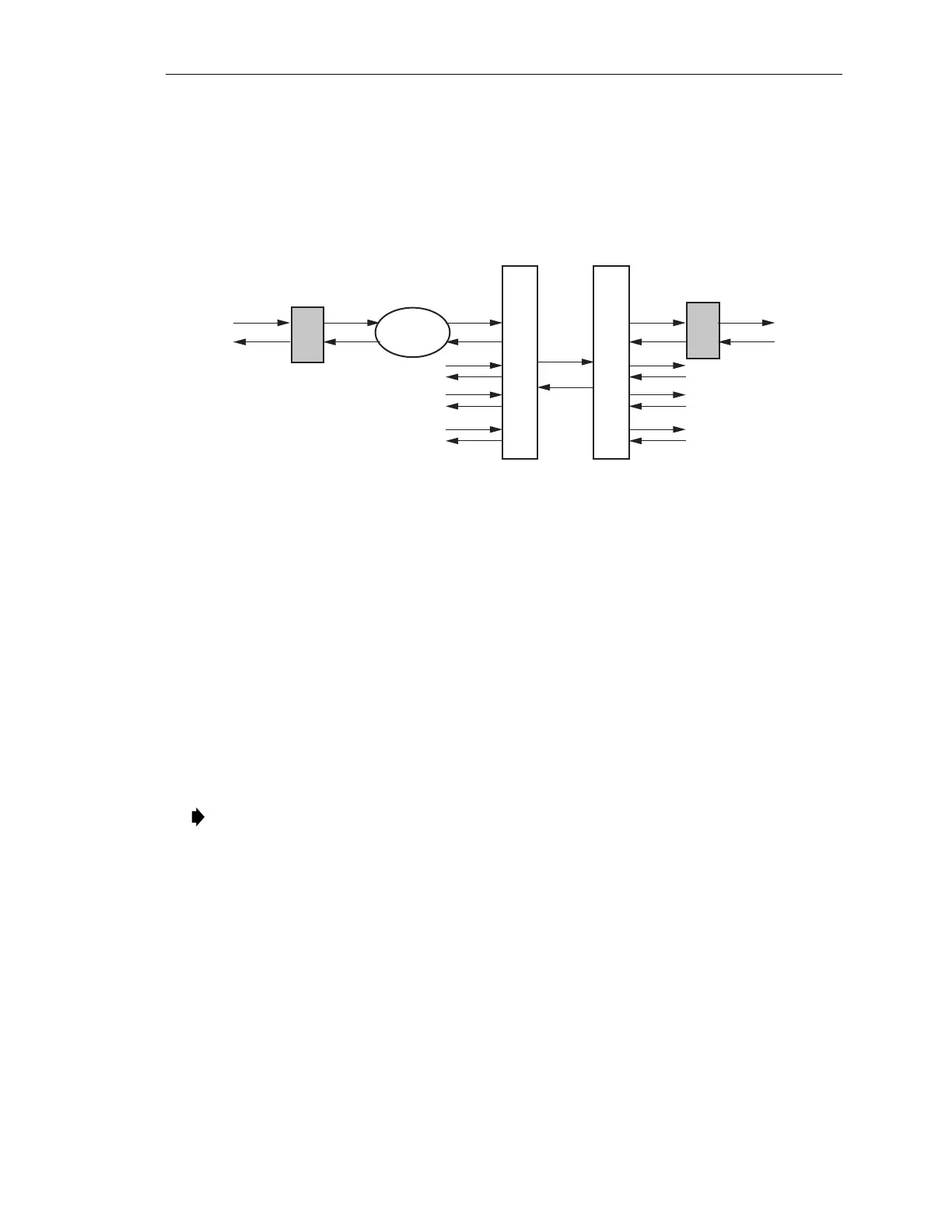
Figure 103-3. Location of Critical Alarm Points on Soneplex QLX System
A
1
= External CSU that will inject PRM (Performance Report Messages) back to
B
1
reporting all DS1 Far End Alarms. This is due to corrupted data received at
A
1
and reported back to
B
1
via the PRM in the FDL (Facility Data Link).
B
1
= QLX DS1 input monitors
T1-1-X-X-1 NEND
PM and alarms. Report measures
the actual DS1 performance as received on transmission from CSU
A
1
.
G
1
= QLX DS1 input monitors
T1-1-X-X-2 NEND
PM and alarms. This report
measures the actual DS1 performance as received on transmit from CSU
H
1
.
H
1
= External CSU at
H
1
will inject PRM back to
G
1
reporting DS1 Far End
Alarms. This is due to corrupted data accumulated in the transmission of the
DS1 from
A
1
to
H
1
transmit direction.
Note:
A
x
indicates DS1 #1 of four possible DS1s.