General Information
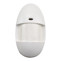
This passive infrared motion detector is designed for use
with control panels that support polling loop devices
equipped with DIP switches or polling loop devices that
require their serial number to be “programmed
*
”. It is a
versatile wall-mounted unit employing Fresnel lenses and
offering efficient protection patterns for commercial and
residential applications. Best coverage will be obtained if
mounting is selected such that the likely direction of
intruder motion is
across
the pattern.
*
If the control panel supports Serial No. programming,
you MUST configure the 998MX as a Serial No. device
(see Address/Serial No. ID section).
This detector is also equipped with “downward looking”
optics to cover the normally “dead” zone directly beneath
a detector.
The detector is shipped with the standard wide-angle lens
installed, but also supports the supplied pet alley lens
(99PA) and long-range lens (99LR). An optional swivel
mounting bracket (998SB) is available (purchased sepa-
rately).
Specifications
Coverage: Standard Wide-Angle Lens
50 ft x 50 ft (15.2m x 15.2m), 90
°
Optional Lens: 99PA, Pet Alley Lens
50 ft x 70 ft (15m x 21.3m), 100
°
99LR, Long Range Lens
100 ft x 10 ft (30m x 3m)
Detection Zones:
W/Standard Lens:
18 zones (9 long range,
5 intermediate, 2 short range).
W/Optional Lenses:
99PA: 12 zones
99LR: 5 zones (1 long range,
2 intermediate, 2 short range).
Detector provides one “downward look-
ing” zone with all lenses (downward look-
ing lens must be masked when using the
99PA).
Pulse Count: Installer-selectable (1, 2, or 3)
Detectable
Walk Rate: 0.5–5 ft/Sec (0.15m –1.5m/Sec)
Mount Height: 7 ft nominal (2.1m)
Indicator:
Red LED with enable/disable link
Input Voltage: 8-11V peak to peak at polling
loop terminals.
Current: 1mA (LED disabled)
3mA (alarm LED enabled)
Standby: Power source should be capable
of at least 4 hours of battery
standby.
Operating Temp:
14
°
F to 122
°
F (-10
°
to +50
°
C)
Humidity: Up to 95% RH (max.),non-
condensing.
Dimensions: 2”W x 4”H x 2”D (max protrusion)
(67mm x 111mm x 54mm).
Installation
Normal Mounting:
Mount the unit to a firm vertical surface.The wall wiring
hole should be no more than 5/16” (8mm) in diameter.
1. Remove the front cover as shown in Figure 1.
2. Refer to Figure 2. Knockout holes “A” in the
base are for normal surface mounting on a
wall (slide PC board up for access to bottom
holes, down for access to top holes). For cor-
ner mounting, see Corner Mounting section.
Also break out the desired wire entry hole at
this time (marked X1 or X2 in Fig. 2).
3. Feed wiring emerging from the wall through
the wire access hole near the top of the
detector base. Make sure wires have sufficient
slack to allow the PC board to be moved up
and down freely when the wires are connect-
ed to the terminals on the board.
4. Mount the base.
Note the mounting orienta-
tion of this detector – wire entry at the top,
lens at the bottom!
5. Refer to the Wiring Connections section
before replacing the front cover.
Corner Mounting:
Knockout holes “B” in the base are used for corner
mounting on a wall (slide PC board up for access to
bottom holes, down for access to top holes). Mount in
selected corner with 4 screws (see Fig. 3).
Note the mounting orientation of this detector –
wire entry at the top, lens at the bottom!
Make sure
the board is positioned so that the arrow is in line with
the appropriate setting on the graduated scale (see
Fig. 5 and Table 1).
Figure 2.
Detector Base
Figure 3. Corner Mounting
Changing lenses (if required)
1. Remove front cover.
2. Release the lens support frame located in
front cover as follows: insert the blade of a
small screwdriver between the locking tab and
the detector case in each of the four corners of
the frame, and lever each tab upward to
release. See Figure 4. When all four corners
are released, remove the lens support frame.
3. Remove the existing lens and replace with the
replacement lens. The lens must be installed
with the smooth side facing outward. Also,
the lens should be oriented with its part
number on the upper right-hand side (see
Fig. 4). Be sure to center the lens.
Note:
Lens surface should be free of dirt,
foreign matter and fingerprints. Use a clean,
dry, soft cloth to wipe lens surfaces.
4. Insert the lens support frame into its original
position and then press downward on the frame
so that the lens locking tabs snap into position in
each of the four corners.