Do you have a question about the ADEMCO VISTA-20P Series and is the answer not in the manual?
| Partitions | 2 |
|---|---|
| User Codes | 48 |
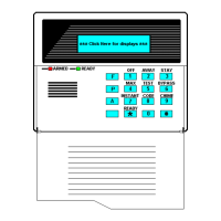
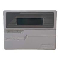
| Keypads Supported | Up to 8 |
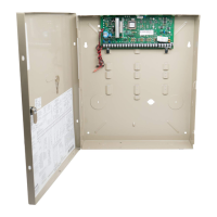
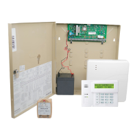
| Hardwired Zones | 9 hardwired zones |
| Battery Backup | 12VDC, 7Ah (recommended) |
| Zones | 9 hardwired zones, expandable to 48 zones with wireless and keypad zones |
| Wireless Zones | Up to 40 with wireless receiver |
| Outputs | 2 onboard trigger outputs |
Settings for phone system selection and communication reporting formats.
Configuration for daylight savings, auto stay arm, cross zone timer, and program mode lockout.
Worksheet for programming zone type, partition, report, hardwire, response time, and location.
Worksheet for mapping output devices like relays and X10 modules.
Worksheet for creating zone lists to control output devices.
Worksheet for defining how functions are activated by zone lists, zone types, or zone numbers.
Details transformer, battery, and charging voltage requirements for system power.
Illustrates wiring for expansion modules (4219, 4229, 4204) and RF receivers (5881 series).