EasyManua.ls Logo

ADEMCO Vista-10SE User Manual

ADEMCO Vista-10SE
100 pages
To Next Page IconTo Next Page
Page #1 background imageLoading...
Page #1 background image
N7227V5 10/00
9
9
,
,
6
6
7
7
$
$
6
6
(
(
6HFXULW\6\VWHP
,QVWDOODWLRQDQG6HWXS*XLGH
*
ARMED
READY
PANIC
OFF AWAY STAY
MAX TEST BYPASS
INSTANT CODE CHIME
READY
1
2
3
654
897
0
*
#
ALARM
CHECK
FIRE
AWAY
STAY
INSTANT
BYPASS
NO AC
CHIME
BAT
NOT READY
®
WWW.DIYALARMFORUM.COM

Table of Contents

Other manuals for ADEMCO Vista-10SE

Question and Answer IconNeed help?

Do you have a question about the ADEMCO Vista-10SE and is the answer not in the manual?

ADEMCO Vista-10SE Specifications

General IconGeneral
KeypadsUp to 8
Power Supply16.5VAC, 25VA transformer
Zones6 zones
Partitions1
CommunicationPhone line
Battery Backup12VDC, 4AH

Summary

RECOMMENDATIONS FOR PROPER PROTECTION

Recommendations for Smoke and Heat Detectors

Guidelines for placing smoke and heat detectors for optimal fire detection coverage.

Recommendations for Proper Intrusion Protection

Recommendations for locating intrusion detection sensors for comprehensive coverage.

SECTION 2 Installing the Control

Standard Phone Line Connections

Wiring instructions for connecting the system to the telephone network.

SECTION 4 Basic Hardwired Zones 1–6

Wiring Hardwired Zones

Instructions for wiring burglary, panic devices, and smoke detectors to zones.

SECTION 5 Wireless Expansion (5800 System)

RF Receiver Installation

Advisories and steps for installing the 5881/5882 RF receiver.

Transmitter Management

Covers jam detection, supervision, input types, and battery life.

SECTION 7 4285 and 4286 VIP Module

VIP Module Installation and Wiring

Instructions for installing, mounting, and wiring the VIP Module.

VIP Module Programming and Operation

Steps to program and test the VIP Module for phone access.

SECTION 8 External Sounders

Sounder Installation and Testing

Covers sounder connections, power, supervision, and testing procedures.

SECTION 10 Audio Alarm Verification (AAV) Unit

AAV Module Overview and Wiring

Explains the AAV module's purpose and provides wiring diagrams.

SECTION 11 Final Power-Up

Grounding and Transformer Wiring

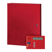
Instructions for earth ground connections and wiring the AC transformer.

System Power-Up and Battery Calculation

Steps for powering up the system and determining battery size.

Backup Battery Connection and Testing

Procedures for connecting the backup battery and performing battery tests.

SECTION 12 Mechanics of Programming

Programming Introduction and Modes

Overview of programming concepts, modes, and requirements.

Data Field and Interactive Programming

Details on data field entry, review, interactive modes, and factory defaults.

SECTION 13 Zone Response Type Definitions

SECTION 14 Data Field Descriptions

System Data Field Explanations

Comprehensive list and explanation of all system data fields for programming.

SECTION 15 Zone Programming

SECTION 16 Output Device Programming

SECTION 18 Alpha Descriptor Programming

SECTION 19 Remote Programming and Control (Downloading)

SECTION 20 System Communication

SECTION 21 System Operation

System Status and Trouble Conditions

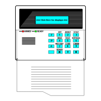
Explains exit error displays, trouble conditions, power failure, and other system messages.

SECTION 22 Testing the System

APPENDIX B Limitations and Warranties

System Limitations and Warnings

Critical limitations, potential failure points, and warnings for alarm systems.
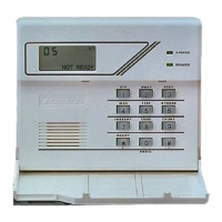
VISTA-10SE SUMMARY OF CONNECTIONS DIAGRAM

Related product manuals