9
4-Installation
Keep these instructions for future reference
All local regulations, including those referring to national standards, must be observed
when installing the appliance.
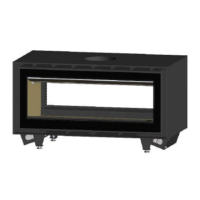
NOTE: If the heater is supplied with base feet, these are to be removed. Remove the door to avoid any
breakage, lay heater on its back and undo the bolts fixing the feet. Feet originally included for transit
with fan installed. If feet are required, ie including fan and using an existing hearth – contact your
supplier
The floor must be structurally sound.
The Hearth must have a heat resistant surface to 600°C, with an insulating thickness of non-
combustible material equivalent to 24mm of cement sheet with thermal resistivity of 0.026m².K/W for
6mm. e.g., Bellis Board or fibre cement sheet equivalent.
Replacement room air from outside equivalent to 314cm2 must be supplied into the room.
The heater must have its own dedicated flue. The active flue must be 8” for the entire length of the
flue, and always less than 45 degrees from the vertical.
The Flue terminal must meet the minimum height and external clearances for the flue, according to
AS/NZ 2918:2001, see the diagram shown below on page 12.
The ADF DUO Linea 100 was tested with a 200mm (8”) triple skin flue kit in a manner confirming to joint
Australia/New Zealand Standard 2918:2001.
The base of the unit is raised 350mm from the floor protector for the following clearances to apply.
AS2918 default clearances apply for installations directly on the floor (75mm concrete slab suspended
with 25mm air gap below – see AS/NZS2918 3.3.3)
A minimum 1450mm deep x 1240mm wide x 6mm thick floor protector (Bellis Board or similar cement
sheet) should be used under and in front and behind the appliance base when installing the appliance
(see joint AS/NZS 2918:2001 3.3.2). The floor protector must extend 450mm in front of both appliance
fuel loading doors and be placed centrally in the 1240mm width. The Thermal conductivity of the floor
protector is 0.026m².K/W for 6mm thick sheets.
 Loading...