Chapter 1 — Overview 5
this chapter discusses the different features, connectors, and
indicators of the PowerLab 2/20 and PowerLab 4/20.
The Front Panel
The front panel of your PowerLab provides most of the connectors for
interfacing with external signals, and indicators for various functions.
This section describes each of the front panel features.
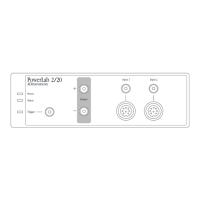
The PowerLab 2/20 has three indicators at the left of the front panel,
one BNC connector for the external trigger, two BNC connectors for
output, and two BNC connectors (marked Input 1 and Input 2) with
two alternative pod (DIN) connectors, for recording external signals.
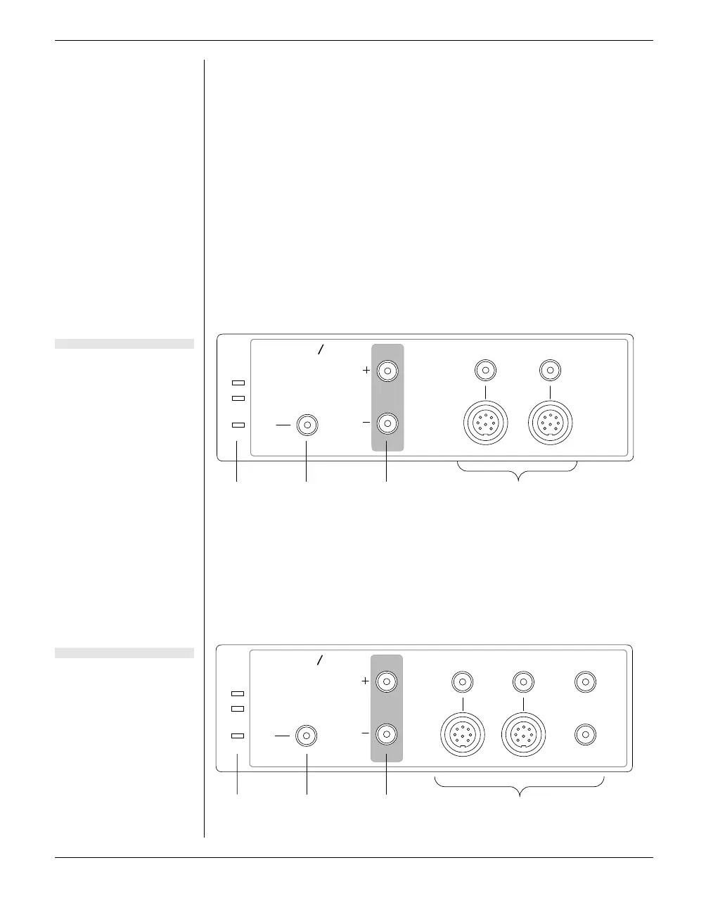
The PowerLab 4/20 has three indicators at the left of the front panel,
one BNC connector for the external trigger, two BNC connectors for
output, and four BNC connectors (marked Input 1 to Input 4) with
two alternative pod (DIN) connectors for Input 1 and Input 2, for
recording external signals.
2 20
Input 1 Input 2
Power
Status
ADInstruments
Trigger
PowerLab
Output
Trigger Analog output connectors Analog input connectorsIndicators
4 20
Power
Status
ADInstruments
Trigger
PowerLab
Output
Input 1 Input 2 Input 3
Input 4
Trigger Analog output connectors Analog input connectorsIndicators
Figure 1–1
The front panel of the
PowerLab 2/20.
Figure 1–2
The front panel of the
PowerLab 4/20.