Owner’s Guide
20
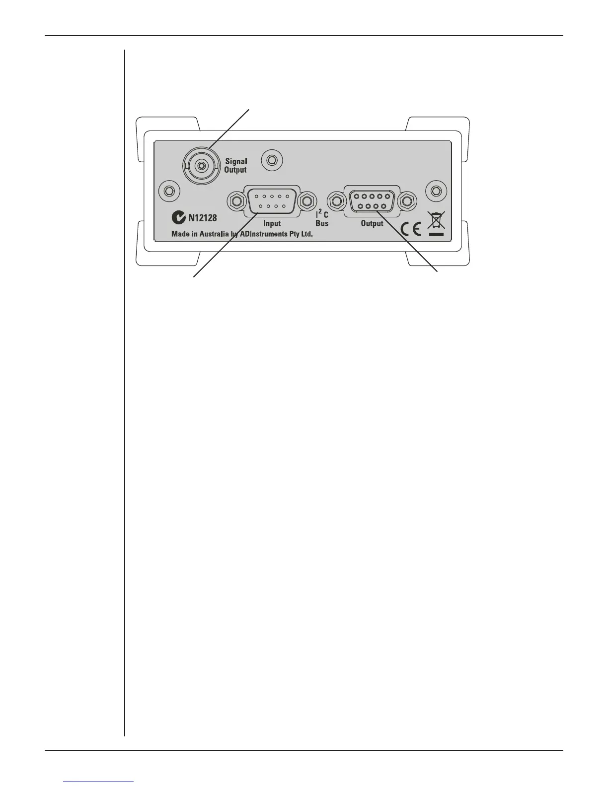
The Back Panel
The back panel of the GSR Amp provides all the sockets required to connect the front-
end to the PowerLab and to other front-ends.
Signal output to the PowerLab
I
2
C connection to
a further front-end
I
2
C connection from the
PowerLab or previous front-end
I
2
C Input and Output Sockets
Two nine-pin sockets are used to communicate with the PowerLab (they are marked ‘I
2
C
Bus’: a ‘bus’ is simply information-transmission circuitry such as cables and connectors).
Power and control signals to the front-ends come from the PowerLab. These I
2
C sockets
allow multiple front-ends to be used independently with one PowerLab. Many front-
ends can be connected to the system, in series, output to input (as discussed in Chapter
2).
The Signal Output Socket
The BNC socket labelled Signal Output on the back panel provides the signal output to
connect to an analog input socket on the front of the PowerLab. A BNC-to-BNC cable is
supplied for this connection.
Connecting to the PowerLab
To connect a front-end, such as your GSR Amp, to the PowerLab, first ensure that the
PowerLab is turned o . Failure to do this may damage the PowerLab, the front-end, or
both.
The BNC cable from the GSR Amp signal output must connect to an analog input on the
PowerLab, for example, Input 1 on a /30 series PowerLab. If you have an older model
PowerLab with di erential (rather than single-ended) inputs, the BNC cable must
connect to a positive analog input on the PowerLab.
Single Front-ends
Connect the I
2
C output of the PowerLab to the I
2
C input of the GSR Amp front-end using
the I
2
C cable provided. Figure 8–3 shows how to connect the GSR Amp to your PowerLab.
Figure 3–2
The back panel of
the GSR Amp