AUTO CAL ZERO
NEXT
-
+
RESET
CYCLE
SNIFFER
SET POINTS SPECTRO
MAINTENANCE
OTHER
F1
F3
F2
F4
10
mbar
hPa
Torr
-3
10
-12
10
-11
10
-10
10
-9
10
-8
10
-7
10
-6
10
-5
10
-4
10
-3
10
-2
10
-2
10
-1
1
10
1
10
2
10
3
COR
mbar l/s
STDBY
INLET PRESSURE
LEAK RATE
EVAC TEST
Pa m
3
/s
Torr l/s
18
17
16
15
20 21 22 23
25 26 27 28
24
19
29
1
11
2
65
7
43
14
13
12
1098
3
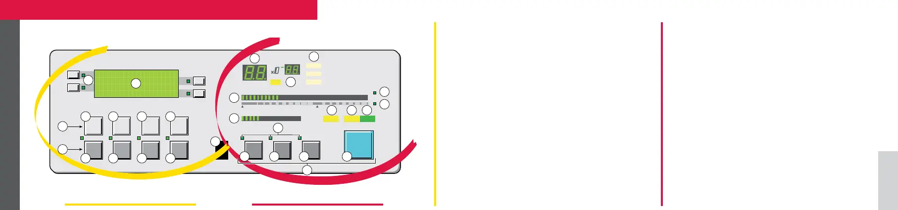
1 Inlet port pressure analog display
2 Control and menu selection indicators (ON when
activated)
3 Auto-calibration START/ABORT control key
4 Sniffing mode ON/OFF control key
5 Auto-zero ON/OFF control key
6 Cycle START/STOP control key
7 Control keys (4 keys)
8 Standby ON/OFF indicator
9 Evacuation ON/OFF indicator
10 Test ON/OFF indicator
11 Helium signal analogic display
12 Helium signal analogic scale ON/OFF indicator
13 Helium signal Zero scale ON/OFF indicator
14 Correction factor COR indicator (applied to digital display)
15 Units ON/OFF indicator
16 Helium signal digital display
17 Alphanumeric display (4 lines x 20 characters)
18 Parameter function keys (1 key per display line)
19 Modification access keys (4 keys)
20 NEXT : next display/parameter circular function
21/22 Plus or minus value adjustment, parameter
selection, audio volume adjustment keys
23 RESET of previously displayed values (cancels tem-
porary inputs)
24 Menu selection access key (4 keys)
25 SET POINT menu selection key
26 SPECTRO calibration and analyzer cell configuration
menu selection key
27 MAINTENANCE menu selection key
28 OTHER menus selection key (test mode selection,
inlet VENT selection, date/time)
29 Remote control connection
Setting and maintenance part Operation part
Operator interface ASM 142/142 D