ADJ Products, LLC - www.adj.com - Pixie Strip 30 / 60 / 120 User Manual Page 8
Pixie Strip 30 / 60 / 120 Installation
FLAMMABLE MATERIAL WARNING!
Keep drive a minimum of 5.0 feet (1.5m) away from ammable material and/or pyrotechnics.
ELECTRICAL CONNECTIONS
A qualied electrician should be used for all electrical connections and/or installations.
DO NOT INSTALL THE DEVICE IF YOU ARE NOT QUALIFIED TO DO SO!
The device MUST be installed following all local, national, and country commercial electrical and
construction codes and regulations.
Before rigging or mounting a single xture or multiple interconnected xtures for custom matrix
designs to any metal truss or structure or placing the xture(s) on any surface, a professional equip-
ment installer MUST be consulted to determine whether the metal truss, structure, or surface is
properly certied to safely support the combined weight of the xture(s), clamps, cables, and any
other accessories.
Fixture(s) should be installed in areas outside walking paths, seating areas, or away from areas
where unauthorized personnel might be able to reach the device by hand.
NEVER stand directly below the xture(s) when rigging, removing, or servicing. Overhead xture
installation must always be secured with a secondary safety attachment, such as an appropriately
rated safety cable (not included) that meets all local, national, and country codes and regulations.
Allow approximately 15 minutes for the xture to cool down before servicing.
SOCKET PIN CONFIGURATION
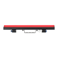
This device features two (2) output sockets on the back side, which may be used to connect the
device to the desired lighting xtures. The pins for each output socket are congured as shown in
the image below. Please consult a qualied electrician for all electrical connections and/or
installations.
Pin 1: Power (+)
Pin 2: Data
Pin 3: CLK (clock pin)
Pin 4: Power (-)
 Loading...