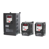
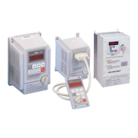
Do you have a question about the Adlee Powertronic MS2-102 and is the answer not in the manual?
General safety and handling guidelines for the inverter before operation.
Explains standard safety symbols used in the manual to indicate hazards.
Details the information presented on the inverter's nameplate for identification.
Guidance on selecting a suitable installation environment to prevent inverter damage.
Recommendation for using nonflammable materials for mounting the unit.
Instructions for proper vertical mounting and required spacing for airflow.
Details the terminals for the main power connections and their functions.
Explains the terminals for control signals, inputs, and outputs.
Description of the function and purpose of each button on the operation panel.
Parameter for setting the initial operating speed of the inverter.
Function to prevent unauthorized modification of inverter parameters.
Parameter to set the time taken to reach the target frequency from zero.
Parameter to set the time taken to decelerate from a target frequency to zero.
Setting for the operating frequency when using the jog mode.
Parameter defining the minimum frequency at which the inverter starts operation.
Enables or disables the jog mode for low-speed operation.
Adjusts the gain for the analog output signal, typically for meters.
Selects the source for frequency input, either analog or digital.
Configures the dynamic braking function or free running mode.
Determines command source for operation, terminal or keypad.
Specifies the primary source for operational commands.
Sets the upper limit for the inverter's output frequency.
Sets the lower limit for the inverter's output frequency.
Configures the scaling for frequency display, including RPM.
Defines the maximum voltage frequency for the first V/F curve.
Lists internal error codes detected by the inverter's self-diagnostic functions.
Details error codes related to incorrect operation or parameter settings.
Essential checks before performing any maintenance procedures on the inverter.
Important considerations before operating the inverter with a motor.
Identifies and provides solutions for power device failures occurring during motor acceleration.
Addresses power device failures during steady-state operation at constant frequency.
Explains causes and fixes for power device failures during motor deceleration.
Details power device failures that occur when the inverter is in a standby state.
Describes errors related to accessing the inverter's EEPROM memory.
Explains EEPROM errors caused by checksum mismatches.
Demonstrates setting up multistage speed control using external resistors.
Illustrates how to configure normal run and jog operation modes.
Shows how to implement a two-stage speed setting using a rheostat.
Details setting up automatic multi-speed operation with timed sequences.
Explains configuring up to eight different speeds via terminal control.
Information on selecting and connecting optional braking resistors for the inverter.
A comprehensive diagram illustrating all terminal connections for the inverter.
Details on the remote operator unit and its accessories.
| Brand | Adlee Powertronic |
|---|---|
| Model | MS2-102 |
| Category | Inverter |
| Language | English |

