Do you have a question about the Adlee Powertronic AS2-122 and is the answer not in the manual?
General guidelines for safe and proper use of the inverter, including checking covers and contacting support.
Explanation of warning and caution symbols used in the manual to indicate potential hazards.
Details on checking the product upon arrival and understanding the nameplate information for model and specifications.
Technical specifications for inverters with single-phase input, including voltage, frequency, and output ratings.
Technical specifications for inverters with three-phase input, covering voltage, frequency, and output capabilities.
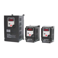
Mechanical dimensions and mounting details for a specific inverter model (Fig 1).
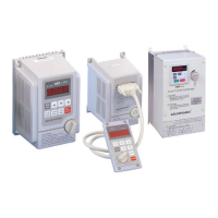
Mechanical dimensions and mounting details for a specific inverter model (Fig 2).
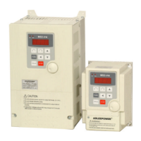
Mechanical dimensions and mounting details for a specific inverter model (Fig 3).
Recommended environmental conditions for inverter installation to ensure optimal performance and longevity.
Diagram illustrating the connections for the main power and motor terminals (L1, L2, L3, U, V, W, P, PR).
Diagram showing the connections for control signals and I/O terminals (FA1, FA2, COM, etc.).
Explanation of hardware configurations, including DIP switches (SW1, SW2) and their settings.
Details on configuring jumper settings for various inverter functions like control structure and relay outputs.
Specifications for wire gauge, type, and torque for main circuit terminal connections.
Guidelines for wiring the main power and motor connections to the inverter, including MCCB and filter.
Recommendations for selecting appropriate wiring equipment like circuit breakers and contactors.
Information on installing surge absorbers on coils of electromagnetic contactors and relays.
Guidance on selecting appropriate cable sizes and managing cable lengths for optimal performance.
Important cautionary notes and best practices for inverter wiring, including main circuit, control signal, and grounding.
Description of the digital control panel buttons, their functions, and operating modes.
Detailed explanation of inverter functions corresponding to display codes CD00 through CD17.
Detailed explanation of inverter functions corresponding to display codes CD18 through CD38.
Detailed explanation of inverter functions corresponding to display codes CD39 through CD60.
Detailed explanation of inverter functions corresponding to display codes CD61 through CD83.
Detailed explanation of inverter functions corresponding to display codes CD84 through CD94.
General instructions and checks before starting test runs and setting inverter functions.
Guide to operating the inverter using panel, RS485, or terminal controls for various functions.
Safety checks and procedures to follow before performing any maintenance on the inverter.
Important considerations and warnings for using the inverter in various application scenarios.
List and explanation of internal errors detected by the inverter's self-checking mechanisms (e.g., EP0, EEP1).
Description of error codes related to operational issues like parameter locking or incorrect commands (e.g., OPE1, OPE2).
Explanation of errors related to communication failures, overheating, overload, and voltage issues.
Example wiring and setup for controlling multistage speed using external resistors.
Example configuration for basic forward/reverse operation and jog mode using terminal inputs.
Example setup for achieving three different speed settings using external controls (VR, SW).
Example configuration for setting up the inverter in a master/slave system using analog inputs.
Specifications and selection guide for optional braking resistors compatible with the inverter models.
Comprehensive diagram illustrating all terminal connections for the inverter's main and control circuits.
Methodologies and factors to consider when selecting the appropriate inverter capacity for a motor.
General guidelines, safety precautions, and recommendations for inverter repair and maintenance.
Checklists for daily and semi-annual inspections to ensure the inverter's proper functioning and health.
| Cooling | Fan |
|---|---|
| Output Voltage | 220V AC |
| Phase | Single Phase |
| Frequency | 50Hz |
| Protection | Overload, Short Circuit, Over Temperature, Low Voltage |