OverflowStandpipeand
DrainLineInstallation
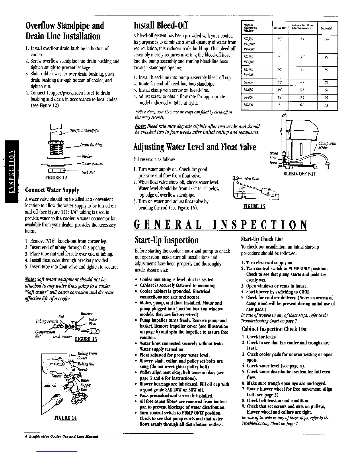
I. Installoverflowdrain bushingin bottom of
cooler,
2. Screwoverflowstandpipe into drain bushingand
tightensnuglyto prevent leakage.
3. Slide rubber washer over drain bushing,push
drain bushing through bouom of cooler, and
tightennut.
4. Connect(copper/pvc/garden hose) to drain
bushingand drain in accordance to local codes
(see Figure 12).
._Over)qow Standpipe
F_
Connect Water Supply
Awatervalveshouldbe installedat aconvenient
locationtoallowthewatersupplytobe turnedon
andoff(see Figure14); 1/4"tubingisusedto
providewatertothecooler.Awaterconnectorkit,
availablefromyourdealer,providesthenecessary
items.
l. Remove7/16"knock-outfromcornerleg.
2. Insertendoftubingthroughthisopening.
3. Plaeetubenutandferruleoverendoftubing.
4. Installfloatvalvethroughbracketprovided.
5. Inserttubeintofloatvalveandtightentosecure.
Note:Softwaterequipmentshouldnot be
attachedtoany waterlinesgoingtoa cooler
"Softwater"willcausecorrosionand decrease
effectivelife ofa cooler
Bracket
ut LockWasher
Faucel Water
InstallBleed-Off
Ableed-offsystemhas been provided withyourcooler.
Its purpose is to eliminatea small quantityof water from
recirculation; this reduces scale build-up. Thisbleed-off
assemblymerelyrequires insertingthe bleed-offhose
into the pump assemblyand routingbleed-line hose
through standpipe opening.
1.Installbleed-lineintopumpassemblybleed-offtap.
2. Routefarendofbleed-lineintostandpipe.
3. Installclampwithscrewonbleed-hne.
4. Adjustscrewtoobtainflowrateforappropriate
modelindicatedintableat right.
Models Gallons Per Hour
Side/Bow_ Molor HP (Recommended)
wlrdow
S/D330 I/3 24
R_5aO
R_4aO0
,_)430 t/3 36
RW4500
S/D430 I/2 42
RgSO00
S/D630 I/2 47
S/I)630 3/4 _ 5
S/08OO 3/4 _5
S/OSO0 I 60
$t,_nd**
140
95
80
7O
60
60
53
*_t _p soa 12-ounce beveragecanfilled by bleed-offin
thisntanyseconds.
Note:Bleedrate maydegradeslightlyaftertwoweeksand should
becheckedtwotofour weeksafter initialsettingand readjusted
AdjustingWaterLeveland FloatValve
Fillreservoir as follows:
1.Torn watersupplyon. Checkfor good
pressure and flowfrom float valve.
2. Whenfloat valveshuts off, check water level.
Waterlevelshould be from 1/2"to 1" below
top edgeof overflowstandpipe.
3. Torn on waterand adjust floatvalveby
bendingthe rod (see Figure 15).
FIGURE15
Clamp with
BLEED-OFFKIT
GENERAL INSPECTION
Start-UpInspection
Beforestartingthe cooler motorand pump to check
outoperation,makesure allinstallationsand
adjustmentshavebeen properlyand thoroughly
made. Assurethat:
• Coolermountingis level;duetis sealed.
• Cabinetis securely fastened to mounting.
• Coolercabinetis grounded.Electrical
connectionsare safeand secure.
• Motor,pump,endfloat installed.Motorend
pumppluggedintojunctionbox (on window
models, theyare factory-wired).
• Pumpimpellertoms freely.Removepumpend
basket.Removeimpeller cover(see illustration
on page6) andspin the impellerto assurefree
rotation.
• Waterlines connectedsecurelywithoutleaks.
Watersupplyturnedon.
• Floatadjustedfor properwaterlevel.
• Blower,shaft,collar,andpulleyset bolts are
snug(do not ovet_ightenpulleybolt).
• Pulleyalignmentokay;belttension okay(see
page3 and4 for instructions).
• Blowerbearingsare lubricated.Fill oil cupwith
agood grade SAE20Wor 30Woil.
• Padspresoakedend correctlyinstalled.
• Allfree aspen fibers are removedfromboUom
panto preventblockageofwater distribution.
• Trimcontsolswitchto PUMPONLYposition.
Checkto see that pumpstartsend thatwater
flowsevenlythrough all distributionoutlets.
Start-UpCheckList
Tocheckoutinstallation,an initialsturt-up
procedureshouldbefollowed:
I. Turn electricalsupplyon.
2. Turn controlswitchto PUMPONLYposition.
Checkto see that pumpstartsandpadsare
evenlywet.
3. Openwindowsor vents in house.
4. Startblowerbyswitchingto COOL.
5. Checkfor cool airdelivery.(Note:an aromaof
dampwoodwill be present duringinitialuse of
newpads.)
In caseof troublein any of thesesteps,referto the
TmublesheotingChartonpageZ
Cabinet Inspection Check List
1. Checkfor leaks.
2. Checkto see that the cooler andtroughsare
level.
3. Checkcoolerpads forunevenwettingor open
spots.
4. Checkwaterlevel (see page 4).
5. Checkwulerdistribution systemfor lull even
flow.
6. Makesuretroughopeningsare unclogged.
7. Rotateblowerwheel for free movement,Align
belt (see page3).
8. Checkbelt tension andcondition.
9. Checkthat set screwsandnuts on pulleys,
blowerwheelend collarsare tight.
te caseof troublein any of thesesteps,referto the
TroubleshootingChartonpage Z
4 _orativeCoolerUseawACareManual
 Loading...