K0022-1 8/01
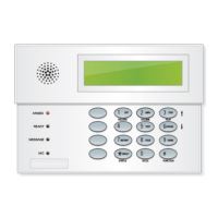
6150VADT & 6160VADT
REMOTE TOUCHPADS
INSTALLATION and OPERATING INSTRUCTIONS
GENERAL INFORMATION
The
6150VADT and 6160VADT
are addressable remote
touchpads designed for use with
ADT
control panels and
provide the following features:
• Backlit Display
• Programmable Function Keys
• Built-in Sounder
• Voice Chime
• Voice Status
• Message Center
Notes:
• When used with the Safewatch Pro/Security
Manager 3000 control panels, address 16 must be
assigned to a single touchpad. Additional
touchpads must be assigned to addresses 17 – 23.
Refer to Setting The Touchpad Options.
• Touchpad keys are continuously backlit for convenience.
• Permanent display backlighting is an option on some
controls (refer to the control panel’s instructions for
details).
• Voice Chime should only be enabled when used with the
SAFEWATCH PRO/SECURITY MANAGER 3000 (a
control panel that supports the "chime by zone" mode).
This mode must be enabled at the control panel. Refer
to the control panel's installation and setup guide for
information on how to program the chime mode.
PROGRAMMABLE FUNCTION KEYS
The Touchpad's programmable function keys [A, B, C, D] are
programmed for panic alarms by default and correlate to the
key pairs for panic alarms shown in the table below. The
programmable function keys may be programmed to support
other special functions. If the programmable functions keys
are programmed to support other special functions the
associated touchpad key pairs still provide the respective
panic alarm (if programmed). Refer to the control panel’s
Installation & Setup Guide for details.
Function
Keys
Equivalent Key Pairs
A
[1] and [*]
B
[*] and [#]
C
[3] and [#]
D
NONE
•
Function keys must be held down for at
least 2 seconds to activate the
programmed function.
•
If functions other than panics are
assigned to the programmable function
keys, programmed panics must be
initiated by pressing the programmed
key pair.
6160vADT-50-001-V0
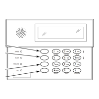
MOUNTING RELEASE SNAPS
(Remove case back by pushing up the 2 "snaps" along
the keypad's bottom edge and pulling the case apart.)
SIDE VIEW
1
23
4
5
6
7
8
9
0
#
STAY
BYPASS
CHIME
INSTANT
AWAY
CODE
TEST
OFF
READY
ARMED
READY
MIC
MESSAGE
RECORD VOLUME
PLAY
STAT US
FUNCTIONVOICE
A
B
C
D
FUNCTION KEY LABELS
A set of adhesive-backed labels with some typical function
symbols (i.e., fire, police, personal emergency, etc.) is
provided. These labels can be placed on or next to the keys
to identify each key's function for the end user (as
determined by the capability and programming of the
control panel; refer to the installation and setup guide for
the control panel).
TOUCHPAD DISPLAYS AND LEDS
The touchpads have the following display features:
Model
Fixed
Word
Display
2-Line
Alpha
Display
2-Digit
Zone
Identifier
Custom
Zone
Descriptors
6150VADT X X
6160VADT X X
The following table identifies the touchpad’s LEDs and
associated functions:
LED Function
ARMED Lights red when the system is armed in any mode.
READY Lights green when the system is "ready" to be armed.
MESSAGE
Flashes red when message waiting or lights red
(steady) when in record mode.
WIRING AND INSTALLATION
Touchpads can be surface mounted using drywall anchors or
to a single- or double-gang electrical box.
1.
Remove the case back
by pushing up the two "snaps"
along the touchpad’s bottom edge and pulling the case
apart. See diagram below.
2.
Route wiring from the control panel
through the
opening in the case back.
3.
Mount the case back
to a wall or electrical box.
4.
Wire directly from the touchpad’s terminal block
to the terminal block on the control board. (See Wiring
Table below.)