61287405F1-22B 3
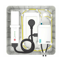
Figure 7. Install UPS
Refer to the UPS LED Status table below for UPS Status.
UPS LED STATUS
For UPS LED Status, refer to the following table.
For UPS Audible Status/Alarms refer to the following table.
Step 5: Install ONT
To install the ONT, refer to Figure 8 and complete the following steps:
1. Orient the ONT as shown and slide the ONT into the ONT
Mounting Clips.
Label LED Status
SYSTEM
STATUS
Green - AC Power load and operating normally
DC Green - Operating off Standby Power
MUTE 2 Flashing - audible alarm silenced for 24-hrs
Solid - audible alarm silenced until manually enabled
BATTERY Service or replace battery, or battery is not installed
Pushbuttons
ALARM
SILENCE
Silence a Battery alarm audible alarm by pressing this button for
more than one second. Press and hold for another 15 seconds to
re-enable alarm function.
N.I.R 1. Allow a “Cold Start” Vdc power from battery pack when AC
line power is not present and new replacement battery pack is
present.
2. Allows for Output Vdc line power reset of ONT when AC line
power is present. Press and hold for 3 seconds to reset/reboot
ONT
State Visual
Indicator
Audible Indicator Description
Replace Bat-
tery
Battery
Indicator
On
1/2 second audible
indicator every 15
minutes
Replace faulty or end of
life battery
Low
Battery
Battery
Indicator
Flashes
1/2 second audible
indicator 4 times per
minute
Battery has reached equal
to or less than 30% remain-
ing capacity on battery dis-
charge
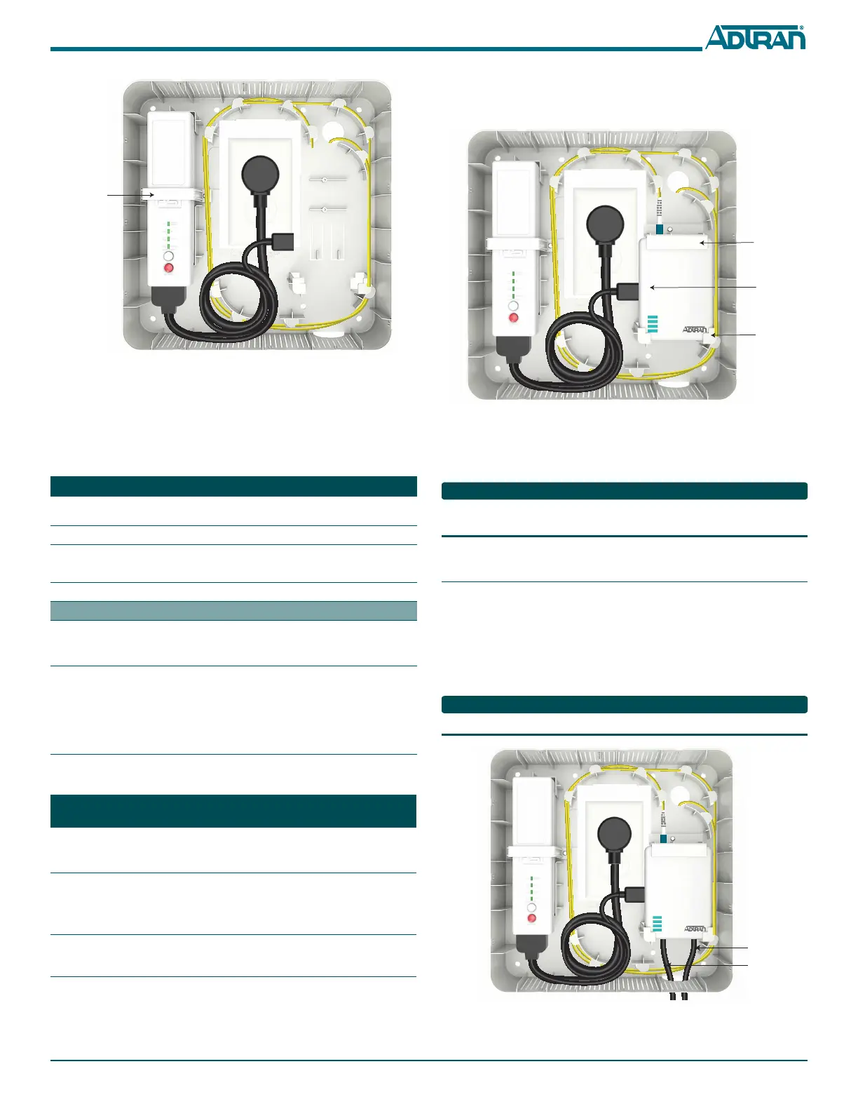
2. Attach the ONT Mounting Bracket and secure with the screw
provided.
3. Connect Power from the UPS to the ONT.
Figure 8. Install ONT
4. Connect incoming fiber.
5. Refer to the ONT LED Status table on the following page to
determine the status of the ONT.
Replace the dust covers on the incoming fiber and optical port on the
ONT when the optical interface in not in use.
Step 6: Connect Ethernet and POTS
To install Ethernet and POTS, refer to Figure 9 and complete the
following steps:
1. Route the Ethernet cable through the cutout at the base of the
Wall Mount Housing and connect to the Ethernet Interface.
2. Route the POTS cable through the cutout at the base of the Wall
Mount Housing and connect to the POTS Interface.
The ADTRAN 401 ONT does not have a POTS Interface.
Figure 9. Connect Ethernet and POTS
ONT Mounting
Bracket
Power fron UP
to ONT
ONT Mounting
Clips
 Loading...