2 PCA-6751 Series Startup Manual
The board has a number of jumpers that allow you to
configure your system to suit your application.
The table below lists the function of each of the board
jumpers and connectors:
Jumpers
Label Function
JP1 COM2 setting for RS-232/422/485
JP2 LCD panel select
JP3 CMOS backup select
JP4 Watchdog timer configuration
JP5 AT/ATX power select
Connectors
Number Function
CN1 FDD connector
CN2 Parallel port connector
CN3 Keyboard lock, LED connector
CN4 USB connector
CN5 24-bit LCD display connector
CN6 36-bit LCD display connector
CN7 LCD inverter connector
CN8 IR connector
CN9 External speaker connector
CN10 Reserved
CN11 VGA connector
CN12 PC/104 connector
CN13 Ethernet connector
CN14 COM2 RS-422/485 connector
CN15 COM2 RS-232 connector
CN16 COM1 RS-232 connector
CN17 External keyboard connector
CN18 ATX power connector
CN20 AT power connector
CN21 Keyboard and PS/2 mouse connector
CN22 ISA gold finger connector
CN23 ISA gold finger connector
CN24 CompactFlash™ card connector
CN25 HDD LED connector
CN26 System reset switch connector
CN27 ATX power button
CN28 Enhanced IDE connector
Jumper settings
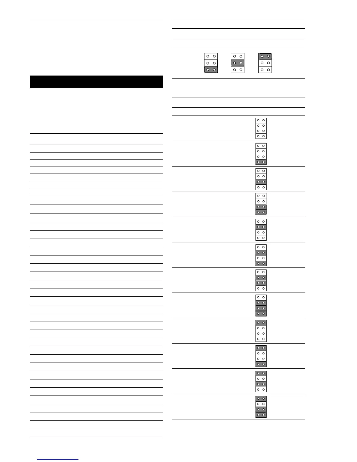
JP1: COM2 settings
*RS-232 RS-422 RS-485
* default setting
JP2: LCD panel select
LCD type JP2
1024 x 600 TFT
48 K
800 x 600 TFT
800 x 600 DSTN2
48 K
800 x 600 DSTN
1280 x 1024 DSTN
48 K
*640 x 480 TFT
18-bit
800 x 600 TFT2
48 K
1280 x 1024 TFT
1024 x 600 DSTN
1024 x 768 TFT
800 x 600 DSTN
48 K
640 x 480 DSTN
Mechanical and Environmental
• Dimension (L x W): 185 mm x 122 mm
• Power supply voltage: +5 V
• Power requirements: + 5 V @ 5 A (typical)
• Operating temperature: 0 ~ 70° C (32° ~ 166° F)
• Weight: 0.3 kg (0.7 lb)
1 2
43
56
12
43
56
12
43
56
1
2
3
4
6
8
5
7
1
2
3
4
6
8
5
7
1
2
3
4
6
8
5
7
1
2
3
4
6
8
5
7
1
2
3
4
6
8
5
7
1
2
3
4
6
8
5
7
1
2
3
4
6
8
5
7
1
2
3
4
6
8
5
7
1
2
3
4
6
8
5
7
1
2
3
4
6
8
5
7
1
2
3
4
6
8
5
7
1
2
3
4
6
8
5
7
Jumpers and Connectors

 Loading...


