PCA-6781 Startup Manual 3
The CD disc contains a driver installer program that will
lead you through the installation of various device drivers
needed to take full advantage of your CPU card.
The computer is provided with a battery-powered Real-time
Clock circuit. There is a danger of explosion if battery is
incorrectly replaced. Replace only with same or equivalent
type recommended by the manufacturer. Discard used bat-
teries according to manufacturer’s Instructions
This device complies with the requirements in Part 15 of
the FCC rules. Operation is subject to the following two
conditions:
This device may not cause harmful interference.
This device must accept any interference received,
including interference that may cause undesired
operation.
1.
2.
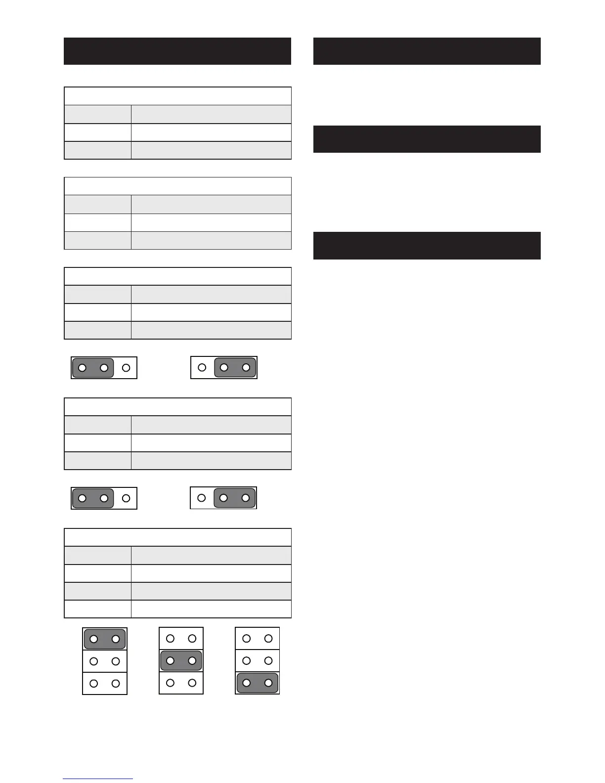
Jumper Setting
J1: LVDS Panel Power Select
Pin
Function
1-2 (Default) +3.3 V
2-3 +5 V
J2: LVDS VBR Select
Pin
Function
1-2 High
2-3 Low
J3: AT/ATX Power choose jumper
Pin
Function
1-2 (Default) ATX Power
2-3 AT Power
J4: Clear CMOS
Pin
Function
1-2 (Default) Normal
2-3 Clear CMOS
J5: COM2 RS-232/422/485 Select
Pin
Function
1-2 (Default) RS-232
3-4 RS-422
5-6 RS-485
Jumpers and Connectors
 Loading...