- 8 -
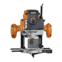
DESCRIPTION
1. Speed selection 18. Collet adaptor
sight windows 19.Spanner 23.8mm (15/16”)
2. Variable speed 20. Parallel guide
control selection 21. Hex nuts
3. Handle 22. Cutter
4. Lock-off button 23. Collet nut
5. Spindle lock button 24. Threaded post
6. Parallel guide lock knob 25. Collet
7. Chip shield 26. Bits
8. Depth stop knob 27. Stop Plunge
9. Stop bar 28. Work-piece
10. Stop bar lock knob 29. Dust port
11. Zero reset indicator 30. Depth of cut
12. Scale 31. Width of cut
13. Power cord 32. 1st pass
14. Plunge lock level 33. 2nd pass
15. Switch 34. Brush assembly
16. Router base 35. Brush cap
17. Sub-base
APPLICATIONS
Use your router only for the purposes listed below:
■ Routing grooves, shaping edges, freehand designs, etc.
in wood.
■ Chamfering, rabbeting, dadoing, and dovetailing in wood.
■ Routing edges on laminates.
FEATURES
Your plunge router is a versatile woodworking tool that will
give you years of trouble-free performance. It is engineered
with the professional in mind, but its ease of operation allows
the amateur to produce work that is beautiful and precise. As
the name implies your plunge router can be used for making
plunge cuts in workpieces, routing grooves,edge routing,
routing circles, and freehand routing. When used with
recommended accessories, such as router table, depth
adjusment knob, and straight guide; it becomes even more
versatile. Various types of cutters, both with and without roller
bearings as guides, also add to the versatility of this tool.
HEAVY DUTY MOTOR
Your router has a powerful motor with sufficient power to
handle tough routing jobs. It delivers 2 horsepower for heavy
duty performance. The motor also has externally accessible
brushes for ease of servicing.
DEPTH STOP SYSTEM
The Accu-Stop™ Micro-Adjustable depth stop located on the
base of your router provides precise stops for repetitive depth
of cut changes. A depth adjustment scale makes quick
adjustments to depth of cut changes possible.
CHIP SHIELD
A plastic chip shield has been provided on the base of your
router for protection against flying dust and chips. It is
designed to fit the front opening of the router base.
SPINDLE LOCK
A spindle lock secures the spindle so that only one wrench is
needed to loosen collet nut and change cutters. NOTE: Do
not run router with spindle lock engaged.
VARIABLE SPEED
Your router has advanced electronic features, designed to
assist you in getting the maximum use from your router. By
making proper speed selections, your router can be adjusted
to specfic routing needs. This eliminates much of the guess
work previously needed to perform operations on router
tables when used with the optional depth control knob.
The variable speed control allows the router to develop a no
load speed that can be adjusted from 15000 to 30000 min .
The variable speed control selector is conveniently located
on the front of the router.
The electronic feature of your router introduces the flexibility
of adjusting the motor speed to required job conditions. An
electronic speed control module senses the load applied to
the motor, and increases or decreases motor voltage to
compensate for and maintain desired RPM.
Speed can be set according to the approximate cutter
diameter you will be using and to the hardness of the
material being cut. The best cuts are made when the cutter is
fed through material at the proper rate of feed.
PLUNGE LOCK LEVER
After extended use, the plunge lock may wear. If this
happens, you can easily adjust the lever.
TO ADJUST PLUNGE LOCK LEVER
■ UNPLUG YOUR ROUTER.
PLUNGE LOCK LEVER SHOWN AFTER
EXTENDED WAER (FIG. 20)
PLUNGE LOCK LEVER SHOWN IN ORIGINAL
LOCKED POSITION (FIG. 22)
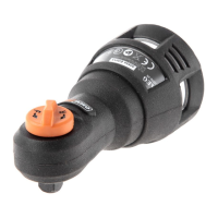
TEMPLATE GUIDE (Fig. 23)
The template guide (36) can be fitted to the base of the
router to accurately duplicate curves and other complex
shape.
These shapes can be easily made by using a jigsaw to cut
out the required designs. Fix the guide to the base of the
router by removing the two screws retaining the dust
extraction port, placing the guide in the recess provided in
the base and replacing the screws. The dust extraction port
must be in place when fitting the guide to hold the screws.
The guide protrudes below the bottom of the base allowing
the router to follow the template. A template must be securely
fixed to the workpiece and a firm pressure applied to the
router at all times to ensure that the edge of the guide
accurately follows the template.
Refer 12/27/04 5:04 PM Page A7
-1