TABLE OF CONTENTS
2
PACKAGE CONTENTS…………………………………………………………………….. 4
SAFETY INFORMATION…………………………………………………………...............5
CASTER INSTALLATION………………………………………………………..................5
CAUTIONS……………………………………………………………………......................6
OPERATING INSTRUCTIONS……………………………………………………………..7
OPERATING INSTRUCTIONS (cont’d) ………………………………………………......8
CARE AND MAINTENANCE……………………………………………..........................13
TROUBLESHOOTING……………………………………………...................................13
WARRANTY……………………………………………………………................………..14
AeonAir.com
TM
!"#$%&'(&)
1. Remove the bucket. 2. Remove the strip of tape that
covers the float switch inside the bucket. 3. Return the bucket to the
unit.
Let unit stand upright for 30 minutes before
powering on.
Unit only reduces humidity when your set humidity is lower
the current room humidity level.
The TIMER MODE:
When unit is operating, it displays the current humidity. Press the TIMER
retfa sdnoces
the
When unit is off, press the TIMER button to set the machine to turn on
5
displaying the timer,
to turn off automatically, as per the below timer
4 hours 8 hours 12 hours Cancel Timer Setting
button to set the machine
timer,
automatically, as per the below timer setting table.
retfa sdnoces
5
confirm the set timer.
41°F (5°C) to 89°F
(32°C).
This machine can automatically turn on/off depending
on your humidity (%RH) setting. Timer mode is to allow you to switch the
ON/OFF at your desired time if you so desire.
Very Humid
Recommended Setting
Very DryVery HumidVV
Recommended Setting
Very DryVV
RH=90%
RH=30%RH=50%
timer.
Before first use:
Before operating:
Operation:
Recommended Operating Temperature Range:
than
unit
displaying
confirm the set
settings table. Timer "off " light will be ON,
room humidity and
Timer " on " light will be ON,
the display will display to turn on time and
the display will change back to current
TIMER SETTING
TABLE:
3
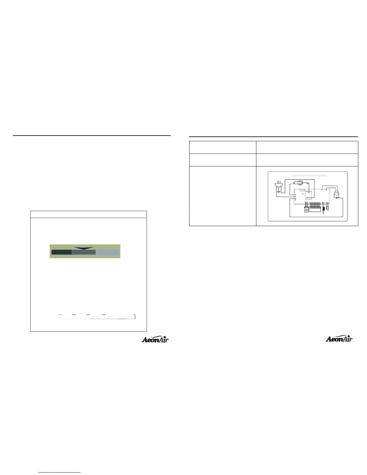
SPECIFICATIONS
Operating environment !"#$%&'#$()*+,%&+,-./
Fuse rating ( type ) 3.15A 250V (3N or 30T)
Schematic wiring diagram
0(The appliance shall be installed in accordance with national wiring regulations.
0(This appliance is not intended for use by children or other persons without assistance or supervision if their physical,
sensory or mental capabilities prevent them from using it safely. Children should be supervised to ensure that they do
not play with the appliance. A damaged cord must be replaced with one supplied by the unit manufacturer and not be
repaired
AeonAir.com
TM
SPECIFICATIONS ...................................................................................................... 3
Schematic wiring diagram
Yellow
CN 1
NO
COM.
CN 3
HI LO
L
N
E
CN 4
CN 2
CN 1
FUSE
P3
N
OLP
3.15A 250VAC
Micro switch
BLUE
T.sensor
Control board
H.sensor
Blue
F/Motor
115V~60Hz
Black
White
Capacitor
Compressor
Red
Red
Blue
White
Black
Capacitor
Black
White
P6
N
P4
N
P5
N
P1
N
P9 P10
 Loading...