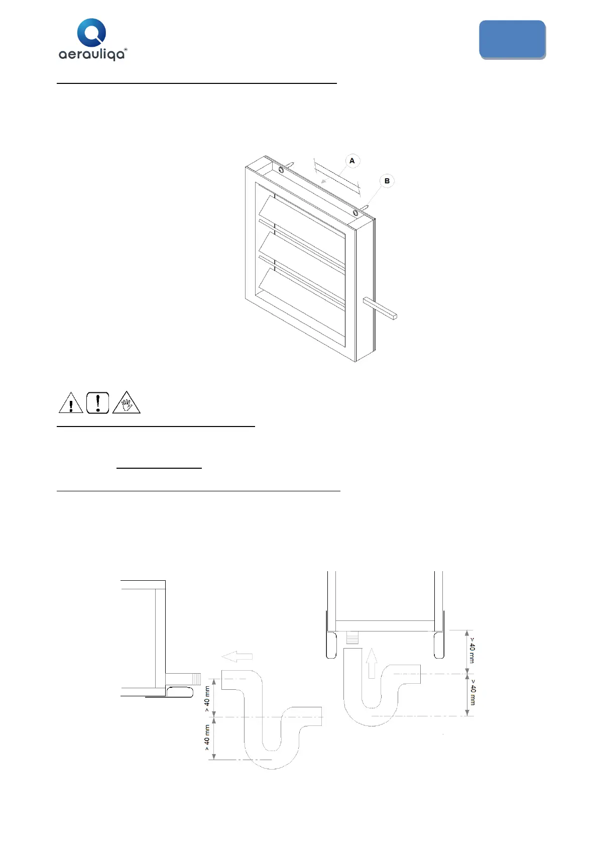
4.6.1 Installation of damper (SKR1, SKR2 supplied apart)
• Each damper is provided with holes on its coupling flange and supplied kit composed of adhesive perimetric
gasket (A) and selfdrilling screws (B), as shown on fig. 10b.
• Apply the gasket all around the perimeter of the flange, place the damper in correspondence with the interested
air intake/outlet so that its shaft is accessible and can't interfere with unit access doors or other functional
elements, then fix by the selfdrilling screws.
4.7 Water and refrigerant connections
The installation and connecting of the piping is an operation that must be done correctly, otherwise it may compromise the
performance of the system. At worst it may cause irreversible damage to the machine. These operations are to be
effectuated by qualified personnel.
4.7.1 Condensation outlet connection (QRCE, CCS, CDX)
• Provide each point of condensation discharge with suitable drain trap, that shall be filled with water before starting
up the unit.
• The drain trap shall be done as shown on fig. 11.
• The drain trap must have a tap for correct cleaning of the lower part, and must allow an easy disassembly.
• The path of the condensation drainage tube must always have a gradient toward external and shall not interfere
with servicing
• Support the weight of discharge piping so as not to load the discharge junction on the unit/external section.

 Loading...