In the back of electrical box panel it is also printed the basic unit external wiring diagram, connection to be carried out by
the installer; wiring diagrams of options are shown on specific sections of Control Manual (see next Chap. 6).
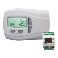
6 – ELECTRONIC CONTROL
Follow instructions of Control Manual supplied with the unit (document code MC00009, valid for all QRCE models).
7 – SCHEDULED AND NOT-SCHEDULED MAINTENANCE
• It is the responsibility of the User to carry out all types of maintenance operations.
• Only personnel previously trained and qualified may carry out maintenance operations.
• Should the unit require disassembly, hand and body protections are required.
Maintenance keeps unit efficiency, reduce the speed of deterioration over time and collect information and data to
understand the efficiency of the unit and prevent failures. We suggest to prepare a booklet of installation according
European legislation. Provide a machine book that allows you to track of the actions taken on the unit, so it will be easier
to cadence adequately the various interventions and will facilitate a possible troubleshooting.
Please take note of: date, type of action, description of action, measurements performed, anomalies identified, alarms
registered in the alarm history, etc. ...
7.1 Scheduled monthly check
7.1.1 Air filters
Air filters are placed close to unit air inlets and are usually accessible :
• for horizontal unit, by lower hinged doors provided with recessed handles and kept closed by blocking devices (by
these doors maintenance is both for filter and fan; fig. 12a)
• for vertical unit, by front hinged doors provided with recessed handles and kept closed by blocking devics (by these
doors maintenance is both for filter and fan; fig. 12b)
Other special access to filter is also possible :
• for horizontal unit, by removing an end side panel provided with recessed handle (fig. 13a)
• for vertical unit, by removing an upper end panel provided with recessed handle (fig. 13b)

 Loading...