MAINTENANCE
19. Using an 11/16” wrench, loosen the
compression fittings on the feedback tube
between the air/fuel valve and the differential
pressure regulator. Remove the feedback
tube (Figure 7.7).
20. Using two 9/16” wrenches, remove the two
3/8-16 hex nuts and bolts securing the
air/fuel valve to the differential pressure
regulator (Figure 7.7).
21. Remove the air/fuel valve, taking care not to
damage the flange “O”- ring.
Figure 7.7
Feedback Tube and Air/Fuel Valve to
Differential Regulator Bolts
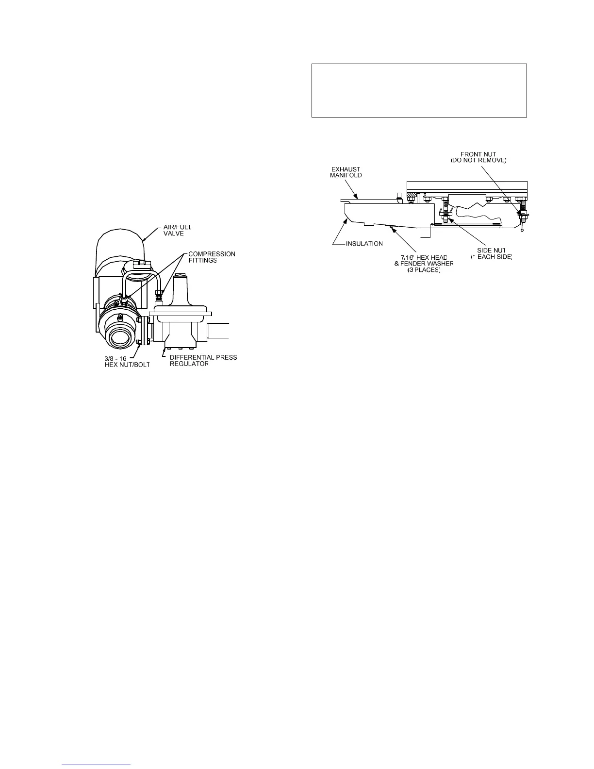
22. Remove the flue venting from the exhaust
manifold.
23. To prevent damage and simplify handling of
the exhaust manifold, it will be necessary to
remove the exhaust manifold insulation.
Using a 7/16” wrench or socket, remove the
3 bolts and fender washers securing the
insulation to the exhaust manifold (Figure
7.8).
24. Loosen the three 1-1/16” nuts that hold the
manifold. Remove the two side nuts. DO
NOT REMOVE THE FRONT NUT (Figure
7.8).
25. Carefully pull the manifold down and back,
removing it through the back of the unit.
26. Inspect the manifold and exhaust tubes for
debris. Clean out any debris as necessary.
27. Inspect the combustion chamber and liner.
Replace the liner if any signs of cracking or
warping are observed.
NOTE:
The combustion chamber liner should be
installed prior to reinstalling the exhaust
manifold
Figure 7.8
Manifold Nut and Bolt Locations
28. Replace the gasket between the manifold
and the combustion chamber (Part Number
GP-122537). The use of Permatex or a
similar gasket adhesive is recommended.
Replace the gasket between the manifold
and tubesheet (Part No. GP-18900). Do not
use any gasket adhesive; this gasket has an
adhesive backing.
29. Beginning with the manifold, reinstall all the
components in the reverse order that they
were removed.
7.7 HEAT EXCHANGER WATER SIDE
INSPECTION
Per CSD-1, the water side of the heat exchanger
requires an inspection. To inspect the heat
exchanger, proceed as follows:
1. Shut off AC power to the unit.
2. Close the supply and return valves to the
unit (Figure 7.9).
3. Open the drain valve and allow the unit to
fully drain. The 1/4 inch plug in the top of
the shell may be removed to aid in drainage
or the relief valve may be opened (Figure
7.9).
7-4
 Loading...