12
Italiano
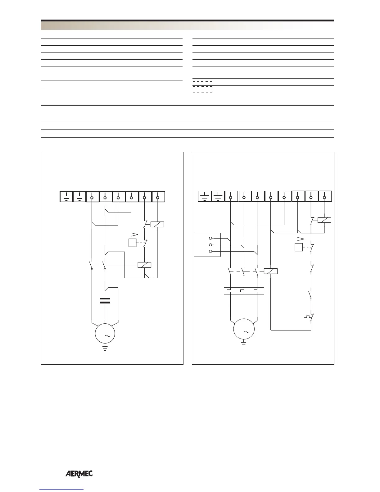
SCHEMI ELETTRICI
AP = Pressostato di alta
CC = Contattore compressore
CMCP = Condensatore di marcia compressore
CP = Compressore
IM = Interruttore di linea
L = Fase d’alimentazione
N = Neutro di alimentazione
PE = Collegamento di terra
PT = Protezione motore
RCS = Relè controllo sequenza fasi
RT = Relè termico
TB = Morsettiera
Collegamenti da eseguire in loco
Componenti non forniti
CWX 1217 1817 1817 T 2417 2417 T
IM [A] 10 16 6 16 6
SEZ. A [mm
2
] 1,5 2,5 1,5 4 1,5
SEZ. B [mm
2
] 1,5 1,5 1,5 1,5 1,5
L1
L
N
N
L
R
N
C
1
Y
P
M
1
CC
CP
AP
2
4
CS R
6
8
1
0
2
A1
A2
R
12
11
CWX 1217 - 1817 - 2417
R
S
T
L1
L1
M
3
L2
L2
L3
L3
N
N
L
R
N
C
1
Y
P
RCS
CC
RT
CP
AP
RT
RCS
PT
1
2
246
RS T
3
4
5
6
A2
A1
95
96
A
C
2
A1
A2
12
11
CWX 1817 T - 2417 T
LEGENDA
DATI ELETTRICI
SCHEMI ELETTRICI
Gli schemi elettrici sono soggetti ad un continuo aggiornamento, è obbligatorio quindi fare riferimento a quelli a bordo macchina.