22
English
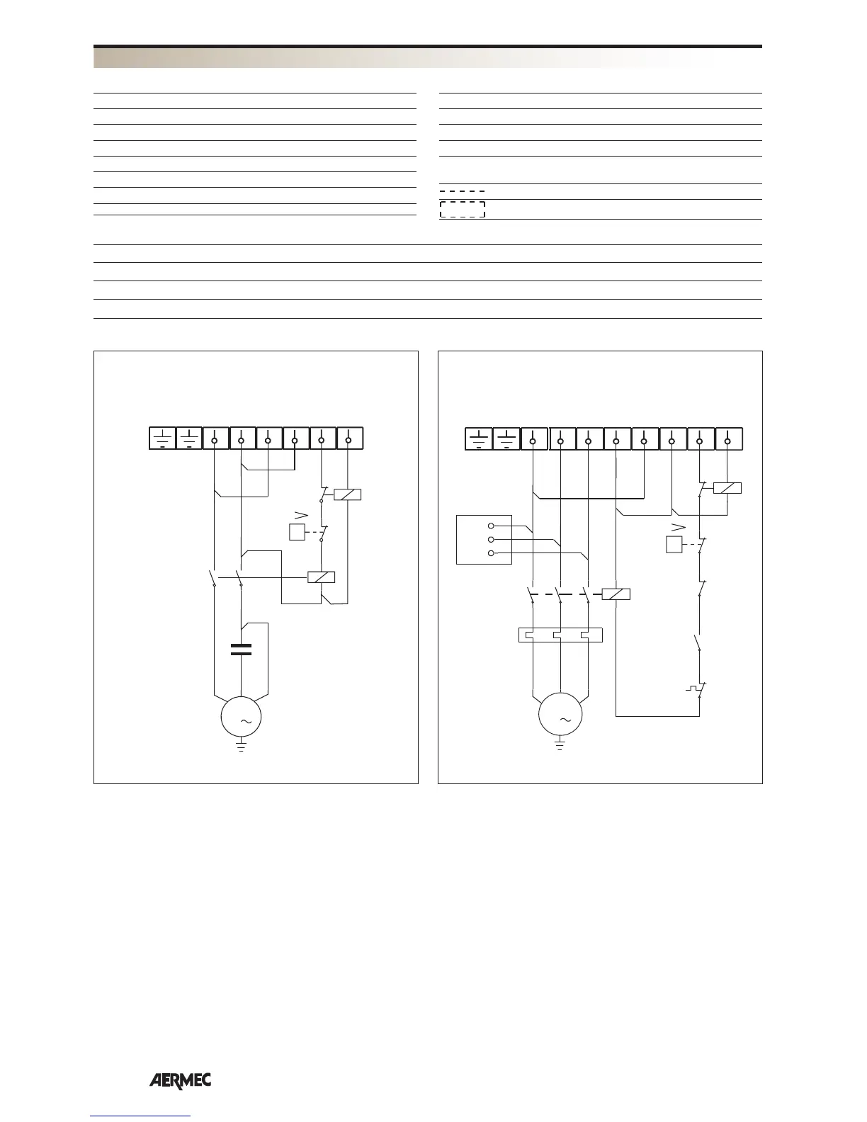
WIRING DIAGRAMS
AP = High pressure switch
CC = Compressor contactor
CMCP = Compressor running capacitor
CP = Compressor
IM = Line switch
L = Feeding phase
N = Feeding neutral
PE = Earth connection
PT = Motor protector
RCS = Phase sequence control relay
RT = Thermal relay
TB = Terminal board
On-site wiring
Components not supplied
CWX 1217 1817 1817 T 2417 2417 T
IM [A] 10 16 6 16 6
SEZ. A [mm
2
] 1,5 2,5 1,5 4 1,5
SEZ. B [mm
2
] 1,5 1,5 1,5 1,5 1,5
L1
L
N
N
L
R
N
C
1
Y
P
M
1
CC
CP
AP
2
4
CS R
6
8
1
0
2
A1
A2
R
12
11
CWX 1217 - 1817 - 2417
R
S
T
L1
L1
M
3
L2
L2
L3
L3
N
N
L
R
N
C
1
Y
P
RCS
CC
RT
CP
AP
RT
RCS
PT
1
2
246
RS T
3
4
5
6
A2
A1
95
96
A
C
2
A1
A2
12
11
CWX 1817 T - 2417 T
WIRING DIAGRAMS KEY
ELECTRICAL DATA
WIRING DIAGRAMS
All wiring diagrams are constantly updated. Please refer to the ones supplied with the unit.