This document provides an installation and maintenance manual for AERMEC NRL FC 028-075 chillers.
Function Description
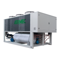
The AERMEC NRL free-cooling series appliances are water chillers designed for industrial applications that require a cooling capacity recovery system called "free-cooling". These units are designed to integrate and eventually replace the cooling capacity delivered by compressors through an additional water cooling circuit that uses the temperature of the external air to cool the system's return water. This design allows for significant energy savings by reducing the operating hours of the compressors, especially in colder climates.
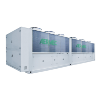
The chillers are available in different configurations to meet various operational needs:
- "A" HIGH EFFICIENCY: Standard high-efficiency models.
- "B" ENHANCED HIGH EFFICIENCY: Models with improved efficiency.
- "D" WITH DESUPERHEATER: Models equipped with a desuperheater for heat recovery.
The operating mode for free-cooling is activated when the external air temperature is sufficiently low to allow water cooling inside the free-cooling coils at the required temperature. This allows the mechanical mode of the unit to operate only with the fans in speed modulation.
For units with both free-cooling and compressors, the free-cooling circuit operates in conjunction with the compressors when the cooling capacity recovered from the external air is not enough to meet the system's required load. The higher the cooling capacity recovered by free-cooling, the lower the integration of the compressors.
When only compressors are used, this mode is activated when the external air temperature is greater than the return temperature of the system water.
Important Technical Specifications
The NRL FC 028-075 chillers are designed for high efficiency and power supply at 60Hz. They use R410A refrigerant. The units are certified by ETL and AHRI, ensuring compliance with industry standards.
Check List (Components):
The manual provides a detailed checklist of components for different versions ("F" and "B" with desuperheater) and hydraulic circuits ("F 00", "P1_P4", and "01_04"). Key components include:
- Cooling circuit: Resistence carter compressor, high pressure switch, low pressure switch, high pressure transducer, low pressure transducer, solenoid valve of hot gas injection, by-pass valve of hot gas, liquid receiver (V/CR), exchanger (desuperheater), and exchanger (glycol free).
- Hydraulic circuit ("F" VERSION): Water filter, flow switch, air vent, pump, expansion tank.
- Hydraulic circuit (Version "P1_P4"): Water filter, flow switch, safety valve, air vent, pump, expansion tank, storage tank.
- Hydraulic circuit (Version "01_04"): Water filter, flow switch, safety valve, air vent, pump, expansion tank, storage tank.
Dimensions:
The chillers come in various dimensions depending on the model:
- NRL 0280 - 0300 FE: 2950 mm (116 in) length, 1100 mm (43 in) width, 1606 mm (63 in) height. A larger version is 3010 mm (119 in) length, 1160 mm (46 in) width, 1750 mm (69 in) height.
- NRL 0330 - 0350 FE: Similar dimensions to 0280-0300 FE.
- NRL 0500 - 0550 FA: 3260 mm (128 in) length, 1100 mm (43 in) width, 1875 mm (74 in) height. A larger version is 3320 mm (131 in) length, 1160 mm (46 in) width, 2035 mm (80 in) height.
- NRL 0600 - 0700 FA: 4010 mm (158 in) length, 1100 mm (43 in) width, 1875 mm (74 in) height. A larger version is 4070 mm (160 in) length, 1160 mm (46 in) width, 1990 mm (78 in) height.
- NRL 0750 FA: 4355 mm (172 in) length, 1500 mm (59 in) width, 1955 mm (77 in) height.
Hydraulic Connections:
The manual illustrates hydraulic connections for NRL 0280-0350 FA and NRL 0500-0750 FA models, showing IN and OUT ports.
Weight Distribution:
Detailed tables provide weight distribution percentages on supporting points for both empty and running units across various models and types (00, P1, P2, P3, P4). This information is crucial for proper installation and structural support.
Electrical Specifications (208V, 230V, 460V, 575V / 3 Phase / 60Hz):
The manual includes tables for LRA (Peak current), MCA (Minimum circuit amperage), and MOP (Maximum overcurrent permitted by the protection device) for different models and voltages, with and without "I" EC inverter fans.
Water Quality Parameters:
Recommended water quality parameters for the hydraulic circuit include:
- PH: 6-8
- Electric conductivity: less than 200 mS/cm (25°C/77°F)
- Chloride ions: less than 50 ppm
- Sulphuric acid ions: less than 50 ppm
- Iron ions: less than 0.3 ppm
- Alkalinity M: less than 50 ppm
- Total hardness: less than 50 ppm
- Sulphur ions: none
- Ammonia ions: none
- Silicone ions: less than 30 ppm
Usage Features
Positioning and Installation:
- The machine is delivered factory-wrapped in shrink film. Before handling the unit, verify the lifting capacity of the apparatus. The removal of packaging and movement of the apparatus must be carried out by qualified and adequately equipped personnel.
- The unit must be installed by a qualified technician in compliance with national regulations and the regulations of the country of destination (Ministerial Decree 329/2004). AERMEC will not assume any responsibility for damages due to failure to follow these instructions.
- Before beginning any operation, users must READ THESE INSTRUCTIONS CAREFULLY AND CARRY OUT ALL SAFETY CHECKS TO REDUCE THE RISK OF DANGER TO A MINIMUM. All the personnel involved must have thorough knowledge of the operations and be vigilant about safety from the moment in which the installation operations are carried out.
- The support surface must be capable of supporting the unit weight.
- The safety differences between the unit and other structures must be checked.
- The inlet and outlet air from the fans must be free to circulate.
- The unit must be installed by an enabled technician in compliance with the technical legislation in force in the country of destination, respecting the minimum technical spaces in order to allow maintenance.
Start-up Procedure:
- After having powered up the unit, preliminary operations must be carried out before the start-up procedure can be completed.
- During the initial loading procedure, two screens are displayed: a start-up screen and a screen to select the system language.
- The system language can be set on the screen displayed at start-up or can be modified at any time through the appropriate screen contained in the Installer menu.
User Interface (PGD1):
- The unit control panel allows quick setting and display of the unit's operating parameters. The parameters are set by default, but users can make any modifications.
- The remote control panel PGD1 allows access to all functions and settings available on the unit.
- After a power failure, the unit is capable of an automatic restart once power is restored.
- The user interface consists of a graphic display with six navigation keys. The display is arranged through a main screen and a series of sub-menus with navigation keys.
- Key Functions:
- ALARM key: Displays the list of active and historical alarms (red LED on = active alarm).
- MENU ACTIVATION key (Prg): Pressing this key activates the navigation between menus (orange LED on = winter operating mode active).
- EXIT MENU key (Esc): Pressing this key returns to the previous menu.
- NAVIGATION (+) key (Up arrow): Pressing this key when navigating between menu/parameters passes to the next menu/parameter. Pressing this key when modifying a parameter increases the value of the selected parameter.
- NAVIGATION (enter) key (Right arrow): Pressing this key when navigating between menus allows entry to the selected menu. Pressing this key when navigating between parameters allows selection of the parameter displayed on the screen. Pressing the key when modifying a parameter confirms the modification of the parameter value selected.
- NAVIGATION (-) key (Down arrow): Pressing this key when navigating between menu/parameters passes to the previous menu/parameter. Pressing this key when modifying a parameter decreases the value of the selected parameter.
Menu Structure and Navigation:
- The unit control panel displays the operating information and functions through a series of menus.
- The operating menus are arranged in a circular fashion, allowing navigation between them.
- The main menu (A) displays current conditions, setpoints, and circuit data.
- Other menus include IN/OUT (B) for advanced information, ON/OFF (C) for enabling/disabling, SYSTEM (D) for operating modes, RECOVERY (E) for heat recovery, INSTALLER (F) for installer settings (password protected), ASSISTANCE (G) for qualified personnel, FACTORY (H) for qualified personnel, and CLOCK (I) for system date/hour settings.
- Navigation is done using the arrow keys and the enter key.
Electronic Control (PCO¹):
- Start-up Circulating Pump: Turn the unit on (ON), start pump, check water flow rate (20 seconds), flow switch or pressure switch (if provided). If no water alarms occur, the compressor starts.
- Anti-freeze Alarm: Compressor block-off at 3°C, on at >3°C. Cod. Anti-freeze alarm (See User Manual). Electrical heater off/on. Circulating pump off/on. Only for pure water (not added with glycol).
- Water Flow Alarm: If the water flow rate is not sufficient, this stops the compressors and the pump. Water flow block-off/on. Flow switch or pressure switch (if provided). Water flow rate is not sufficient (Compressor does not work). Cod. Alarm (See User Manual). Water flow is sufficient (>20 seconds, Start Compressor).
Auxiliary Connections:
The manual provides diagrams for remote control (PGD1), circulating pump (J12-N01, J22-N018), external alarm (J15-N08/C8/NCB), and external circuit breaker (J20-IDC17). The address to enable the remote panel is 31.
Maintenance Features
Hydraulic Circuit Maintenance:
- System Load: Before starting the load, check that the system drain tap is closed. Open all the drain valves of the system and of the related terminals. Open all the devices of the system. Start the filling by slowly opening the water bypass valve. Wait until the system is full. When water begins to flow from the terminal vent valves, close them. Continue filling up to load on the gauge the value of 1.5 bar. The system is loaded at a pressure between 1 and 2 bar. It is advisable to repeat this operation once the machine has worked for some hours to automatically check the system pressure, restoring it if it drops below 1 bar. Check the hydraulic seal of the joints.
- Emptying the System: Before starting to drain the system, turn "off" the unit. Check that the water system load/restore tap is closed. Open the drain tap outside the machine and all the vent valves of the system and the corresponding terminals. If the system uses glycol, this liquid should not be drained to the environment because it is a pollutant. It must be collected and, if possible, reused.
- ATTENTION: In case of version with pumping unit, for the correct operation, it is recommended to install unidirectional valves to the delivery of each pump. So water reflux is avoided in the pump or the pump's from the other circuit.
- It is necessary that the water flow rate to the chiller unit complies with the values reported in the performance tables.
- The systems loaded with anti-freeze or special glycol do not need the water backflow system.
- Special supply/recovery water is carried out with appropriate treatment systems.
- Carefully wash the plant, before connecting the unit. Cleaning will eliminate any residues such as shavings, dirt, or other impurities from the pipes. These substances could deposit inside and cause the exchanger to malfunction. The connection pipes must be suitably supported so as not to burden the apparatus with their weight.
- The choice and installation of components external to the NRL unit to the machine must be done at a rate according to the rules of good technique and in compliance with the regulations in force in the country of destination.
- The hydraulic pipes connecting to the machine must be properly sized to ensure the water flow rate required by the system in operation. The water flow to the exchanger must always be constant.
- The electrical parallel is in charge of the installer.
Electrical Wiring Maintenance:
- The NRL chillers are completely wired and only need the connection to the power supply net, downstream to a group switch, according to the local regulations in force in the country where the machine is installed.
- It is suggested to check:
- The mains supply characteristics, to ensure it is suitable for the levels indicated in the electrical data table, also taking into consideration any other equipment that may be operating at the same time.
- The unit is only powered after the last (hydraulic and electrical) connections.
- Follow the connections instructions of the phase conductors (L1, L2, L3).
- The power line will have a special protection upstream against short circuits and overloads that sections the system according to other users.
- The voltage should be within a tolerance of ± 10% of the nominal value.
- For three-phase units, displacement max 3% between the phases. If these conditions are not met, contact the energy supplier.
- For electrical wirings, use isolated conductors according to the standards in force in the different countries.
- It is necessary to use a omnipolar thermomagnetic switch or fuses appropriate to the standards (contact opening of at least 3 mm), with adequate section cables, as specified in the table based on the followed electrical data table, installed as close as possible to the machine.
- It is necessary to carry out an efficient earth connection. The manufacturer can not be held responsible for any damage caused by the absence of an efficient earthing of the machine.
- After connecting the three-phase power, check the correct connection of the phases.
- WARNING: Forbids to use water pipes for the earthing of the machine.
- Recommended Section of Electric Cables: The cable sections indicated in the table are advised for a maximum length of 50 m. For higher lengths or different types of cable installations, it is NECESSARY to carefully measure the line main switch, the supply power line and the machine connection, and the wiring connection cables.
- ATTENTION: All electrical operations must be carried out by qualified personnel, in compliance with the local bonding regulations, trained and informed about the risks related to these operations.
- The characteristics of electric lines and protection devices must be established by personnel authorized to design electric installations, following national regulations and the national regulations of the country of destination, and installed, in compliance with the legislation currently in force at the moment of installation.
- For installation requirements, the tables herein supplied with the unit must be compulsory referred to. The unit must be supplied with the manuals kept in good conditions and readily available for future operations on the unit.
- It is compulsory to check the machine sealing before connecting the electrical wiring. The machine cannot be powered once the hydraulic and electric operations are completed.
- Field wiring by others which complies with National Electrical Code & Local Codes.