EasyManua.ls Logo

AERMEC PXA R - User Manual

AERMEC PXA R
8 pages
Print Icon
To Next Page IconTo Next Page
Loading...
ISO 9001 - Cert. n° 0128/4
APXARUJ
0609
5073900_01
PXA R
PANNELLO COMANDI ELETTRONICO PER
VENTILCONVETTORI CON RESISTENZA ELETTRICA
INSTALLAZIONE A BORDO DEL VENTILCONVETTORE O A PARETE
ELECTRONIC CONTROL PANEL FOR FAN COILS WITH
ELECTRIC HEATER
WALL-MOUNTED OR ON BOARD INSTALLATION
PANNEAU DE COMMANDE ELECTRONIQUE POUR
VENTILO-CONVECTEURS AVEC RÉSISTANCE ÉLECTRIQUE
INSTALLATION MURALE OU SUR L'APPAREIL
ELEKTRONISCHE BEDIENTAFEL FÜR
GEBLÄSEKONVEKTOREN MIT ELEKTRISCHEM
HEIZREGISTER
ZUR WANDMONTAGE ODER ZUM EINBAU IN DER MASCHINE
TABLERO DE MANDOS ELECTRÓNICO PARA FAN COILS
CON RESISTENCIA ELÉCTRICA
INSTALACIÓN EN FAN COIL O A PARED
MANUALE D’USO E INSTALLAZIONE
USE AND INSTALLATION MANUAL
MANUEL D'UTILISATION ET D'INSTALLATION
BEDIENUNGS- UND
INSTALLATIONSHANDBUCH
MANUAL DE USO E INSTALACIÓN
Question and Answer IconNeed help?

Do you have a question about the AERMEC PXA R and is the answer not in the manual?

AERMEC PXA R Specifications

General IconGeneral
BrandAERMEC
ModelPXA R
CategoryThermostat
LanguageEnglish

Summary

Operation Modes

Ventilation Control

How the thermostat controls fan speed and operation based on water temperature for heating/cooling.

Heating Element Operation

Electric heater activation when water temperature is insufficient for normal heating.

Automatic Changeover System

Automatic switching between heating and cooling modes based on system conditions.

User Interface and Controls

Speed and Temperature Selectors

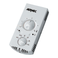
Explanation of the speed selector (A) and temperature selector (B) for device operation.

Frost Protection Mode

Functionality to prevent freezing in unused rooms by maintaining a minimum temperature.

Indicator Light Displays

Description of the indicator lights (LEDs) and their meaning for working modes.

Dip-Switch Configuration

System Settings and Functions

Details on dip-switch settings for various system configurations and functionalities.

Installation Procedures

Wall Mounting Guide

Instructions for mounting the control panel on a wall, considering placement and environment.

On-Machine Mounting

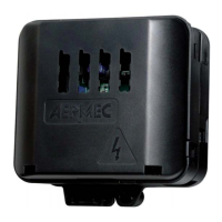
Guidance for attaching the control panel directly onto the fan coil unit.

Installation Autotest

Procedure to activate an Autotest mode for checking loads and functions after installation.

Electrical Schematics and Cables

Wiring Diagram Legend

Key to understanding symbols and abbreviations used in wiring diagrams.

Connection Cable Specifications

Requirements for cable types and insulation for various connection scenarios.

Technical Electrical Data

Power Supply Specifications

Details on voltage, frequency, input power, and grounding requirements.

Output Terminals

Information on fan control outputs (V1, V2, V3) and valve control.

Input Terminals

Details on sensor inputs (water, remote contact) and their requirements.

Environmental Conditions

Operating temperature, humidity, and pollution degree specifications.

EC Conformity Standards

Compliance with electromagnetic compatibility and low voltage directives.

Related product manuals