Do you have a question about the AERMEC VMF-E18 and is the answer not in the manual?
Covers accumulation and protection measures against static electricity.
Includes warnings on voltage, cable handling, and malfunction procedures.
Details the packaging of the thermostats.
Explains the thermostat's communication within a TTL network.
Describes the requirements for cooling operation.
Describes the requirements for heating operation.
Details automatic selection between heating and cooling modes.
Details system response to faulty ambient temperature probes.
Explains how slave fan coils manage faulty ambient probes.
Describes the functionality of the electric heater.
Covers the activation and function of purifying devices.
Provides configuration settings for 2-pipe systems.
Provides configuration settings for 4-pipe systems.
Describes the setup and configuration of the TTL network.
Provides essential instructions for safe and correct electrical wiring.
Details the mounting and connection of the thermostat housing and board.
Highlights critical safety precautions for electrical connections.
Lists all connectors and their specifications for the electronic board.
Shows the layout and connections of the electronic board.
Explains the functions controlled by the dip-switch settings.
Details how to select the system type using dip-switches.
Lists power supply, inputs, outputs, and environmental ratings.
Details specific connections for power, accessories, and serial communication.
Shows connections for power supply and inverter module.
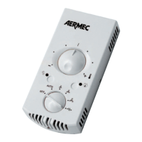
Illustrates how to connect the control panel to the board.
Details connections for TTL and RS485 serial interfaces.
Shows connections for presence sensors and external contacts.
Illustrates connections for air and water temperature probes.
Details the connection for the microswitch.
Details RS485 serial supervision setup with VMF-E5.
Shows RS485 connection with external power supply for VMF-E5.
Illustrates RS485 serial connection between two VMF-E18 units.
Details RS485 serial connection of VMF-E18 with MODU-485A.
Shows RS485 serial connection of VMF-E18 with VMF-MCR.
Presents the overall electrical wiring diagram for the VMF-E18 unit.
Provides a key to understand the symbols and abbreviations used in the wiring diagrams.
Displays the electrical wiring diagram for the VMF-E1 unit.
Displays the electrical wiring diagram for the VMF-E2/E4 units.
Illustrates the wiring for a master unit and slave 1 in a network.
Shows the wiring for slaves 2 through 5 in a network configuration.
Details RS485 and TTL connections in master-slave setups.
Shows how VMF-E5 integrates into the master-slave network.
Illustrates the TTL serial connection from master to slave 1.
Shows the TTL serial connection from slave 1 to slaves 2-5.
Details RS485 supervision setup with VMF-E5 power supply.
Illustrates TTL serial connections for local communication.
Shows RS485 supervision with external VMF-E5 power supply.
Provides diagrams for TTL and RS485 interface connections.
Details RS485 connection to MODU-485A module.
Shows RS485 connection to VMF-MCR module.
Illustrates RS485 connection between VMF-E18 and VMF-MCR.
States that technical data is not binding and Aermec reserves modification rights.
Provides contact details and website for Aermec S.p.A.
| Protection Rating | IP30 |
|---|---|
| Display | LCD |
| Communication | Modbus RTU |
| Operating Temperature | 0°C to +50°C |
| Outputs | 2 relay outputs |
| Relative Humidity | 5% to 95% (non-condensing) |