19
AVMFE18LJ1101 - 6795746_02
BOARD INSTALLATION AND CONNECTIONS
• The VMF-E18 Kit includes the
system with connection cables
to the Inverter Control Module.
The cables are wired with connectors
for quick connection.
The installation of the VMF-E18 kit
requires that standard control board
and connection cables to the Inverter
Control Module (Signal and Supply) are
removed from the fan coil.
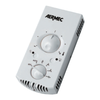
• Mount the thermostat housing to the
side of the fan coil units, on the con-
nections that were of the control board.
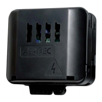
• Remove the cover of the thermostat
housing.
• Connect the inverter control module
VMF-E18 to the thermostat using
the system with connection cables
supplied with the VMF-E18 kit.
Check the connection with the wiring
diagram.
• WARNING: make an earth connection
for the thermostat board.
DANGER: it is compulsory to tighten the
screw on the side of the fan coil, as this
is what allows the earth connection of
the entire system.
• Connect the power supply cables. Warn-
ing: respect the L and N polarities.
• Connect the electric cables of the air
temperature sensor (SA).
• Connect the electric cables of the water
temperature sensor (SW).
• Connect the electric cables of the sec-
ondary water temperature sensor (SW1),
in 4-pipe hydronic systems.
• Connect the cables for the external
contact (if envisaged).
• Connect the cables for the presence
sensor (if envisaged).
• Connect the cables for the microswitch
(if envisaged).
• Connect the mains and RS485 power
supply cables (if connected to the
mains). DANGER: must be connected
to the earth.
• Connect the TTL mains cables (if con-
nected to the mains).
• Connect the cables of the control panel
(if envisaged).
• Check that all the connections and rela-
tive cables are well fixed.
• Arrange the cables so there is no risk
of them being cut, crushed, jerked,
scraped, or generally damaged.
• Check that the board fuse is undamaged
and possesses the necessary features.
• Close the housing with the cover.
• Fix the power supply cables and valve
cables using the cable clamp.
DANGER: it is compulsory to tighten the screw on the side of the fan coil, as this is
what allows the earth connection of the entire system.
WARNING: Keep separate electri-
cal connections from water con-
nections. Water connections and
drain should be on the side oppo-
site of the electrical connections.
 Loading...