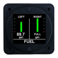
FL20X Installation Instructions
Document # S200-FL20X-002
Rev 1.4 02/28/2017
Page 1 of 1
Tel. 416-628-0725
www.aerospacelogic.com
1. The FL20X instrument uses resistive, float type senders for fuel level sensing.
Ensure that all senders are in a good working condition BEFORE proceeding to
step 2.
a. FL20X instruments use the existing aircraft fuel senders. For tanks with
multiple senders, ensure that the senders are connected in series with the
outermost sender in the series being grounded. The sender array must
represent a varying resistance with relationship to fuel level and NOT be
powered from any source.
b. FL20XD instruments use magnetoresistive aircraft fuel senders P/N
CC284022-()-(). Install in accordance with the manufacturer supplied
instructions for these senders.
2. Connect the wiring supplied with the DB25 interface connector in accordance
with the FL20X Wiring and Installation Schematic. DO NOT ATTACH THE
CONNECTOR TO THE INSTRUMENT UNTIL ALL WIRING HAS BEEN
CONNECTED.
3. Select the instrument location in the aircraft panel.
4. Ensure that the aircraft master switch and/or power to the instrument is OFF.
5. Attach the DB25 connector to the instrument. Ensure that the plug is fully
inserted into the instrument. Finger tighten the two plug locking screws, then
tighten 1/8 turn using a screwdriver. DO NOT OVERTIGHTEN.
6. The instrument can be installed with the DB25 connector orientated to the TOP
or BOTTOM of the instrument panel.
7. Install the instrument in the panel, attaching with four 6-32 X 5/16” screws.
8. Initial Power Up Sequence:
a. Adjust the instrument intensity control for maximum intensity.
b. Apply power to the instrument.
c. The instrument display will turn on. Ignore the orientation at this time.
d. Turn the instrument OFF.
9. If the instrument display does not turn on:
a. Ensure intensity control is set for maximum.
b. Turn off power.
c. Disconnect the DB25 connector from the instrument.
d. Check intensity control.
e. Check the wiring installation and breaker or fuse.
10. Proceed to “Instrument Setup”.

 Loading...