EasyManua.ls Logo

Aerospace Logic FL20 Series User Manual

Aerospace Logic FL20 Series
14 pages
To Next Page IconTo Next Page
Page #1 background imageLoading...
Page #1 background image
Aerospace Logic Inc.
Tel. 416-628-0725
www.aerospacelogic.com
This document set is applicable to the following part number configurations:
Part Number
Description
FL202
Fuel level instrument, two tanks,
resistive senders
Part Number
Description
FL203
Fuel level instrument, three tanks,
resistive senders
Part Number
Description
FL204
Fuel level instrument, four tanks,
resistive senders
Part Number
Description
FL205
Fuel level instrument, five tanks,
resistive senders
Part Number
Description
FL206
Fuel level instrument, six tanks,
resistive senders
Question and Answer IconNeed help?

Do you have a question about the Aerospace Logic FL20 Series and is the answer not in the manual?

Aerospace Logic FL20 Series Specifications

General IconGeneral
TypeFuel Level Indicator
DisplayDigital
MountingPanel Mount
Display TypeLED
Accuracy±1%
Resolution0.1%

Summary

FL20X Fuel Level Resistive

NO NONSENSE WARRANTY

FL20X Installation Instructions

Initial Power Up Sequence

Steps for initial power up and display check of the instrument.

Intensity Control – Installation Options

Preferred Method – Independent Potentiometer

Connecting the intensity control to an independent potentiometer.

Connection of Existing Panel Intensity Control

Connecting the intensity control to the existing panel lighting control.

Day VFR Operation

Setting intensity control for Day VFR operation without external connection.

FL20X Wiring and Installation Schematic

200 Series Human Interface Definition

Top Button

Defines the function of the top button for various operations.

Bottom Button

Defines the function of the bottom button for navigation and selection.

Intensity Control

Procedure to access and adjust the dimmer control menu.

FL20X Instrument Setup

Information Required for Setup

Details information needed for setting up each tank.

Calibration Procedure

Step-by-step guide for calibrating the instrument with fuel.

FL20X Operations Guide

Power Up / Default Screen

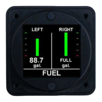
Displays fuel level in each tank and tank indicators.

Trend Graph

Provides a graphical display of fuel usage over time.

Other Options

Accessing instrument serial number and core information.

FL20X Product Specifications

FL20X Installation Compliance

Installation Procedures and Limitations

Guidelines for installation, including procedures and model list.

Installation Location and Visibility

Recommendations for instrument placement and pilot visibility.

TSO COMPLIANCE NOTICE

Information regarding TSO approval and aircraft installation standards.

Related product manuals