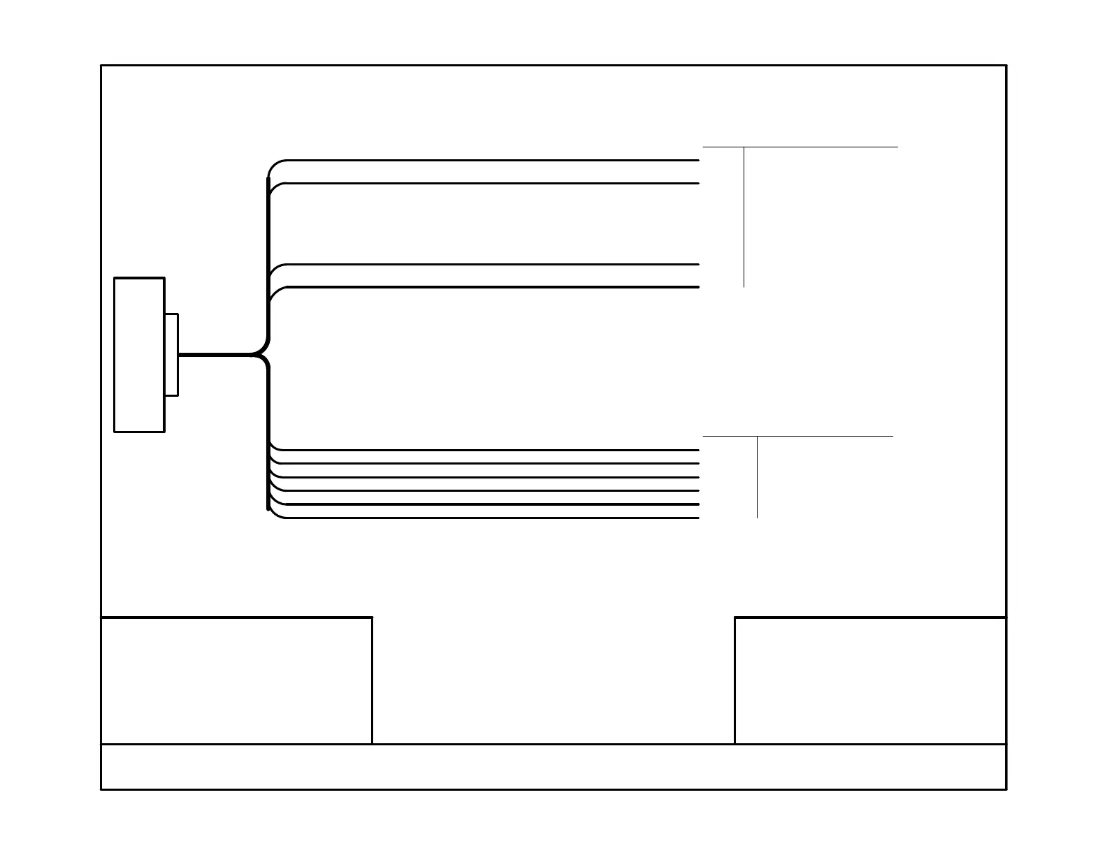
FL20X Wiring and Installation Schematic
S200-FL20X-003 Rev 1.4 02/28/2017
DB25 CONNECTOR
FL20X INSTRUMENT
RED
BLACK
ORANGE
6V - 36V SUPPLY
GROUND
EXTERNAL ALARM (MAX 100mA SINK)
COLOR DESCRIPTION
WHITE / #4
WHITE / #5
WHITE / #6
COLOR/TAG TANK NAME (DISPLAYED)
(C) Aerospace Logic Inc. (2008-2017)
NOTES:
1. * See S200-DDC-INST for additional intensity control options
Resistance grearter than 10 and less than 300 ohms1.
INSTALLATION NOTES:
Allow for current drain of 0.1A (100mA)
Install using breaker or panel fuse
Maximum 7 instruments per 1A of breaker capacity
For multiple instrument installations install breakers to comply
with redundancy requirements of AC 23.1309-1D Appendix 1
1.
2.
3.
4.
1
2
3
SENDER NOTES:
2. Multiple resistive senders per tank to be connected in series
3. Qualified for use with OEM or STC'd senders only
WHITE / #1
WHITE / #2
WHITE / #3
4
5
6
BLUE 0V-BUS VOLTAGE - VARIABLE INTENSITY INPUT *
TANKS NUMBERED LEFT TO RIGHT
(FUEL / LEFT / 1)
(RIGHT / 2)
(3)
(4)
(5)
(6)
NUMBER OF WHITE WIRES TO MATCH TANK CONFIGURATION
Frequency input greather than 10Hz and less than 300Hz
 Loading...