Do you have a question about the AEV MIRAGE MK III and is the answer not in the manual?
Provides an overview of the MIRAGE AM Audio Processor as a complete audio signal processing system for AM transmission.
Explains the MIRAGE's dynamic control over audio signal levels and peak limiting for FM transmission, ensuring clear sound.
Defines average and peak values in sound, explaining how peak/average ratio affects sound quality and the role of clipping.
Instructions for initial power-up, emphasizing voltage checks and proper grounding of the MIRAGE unit.
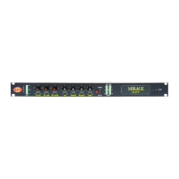
Details the functions of the front panel controls, including LED bar displays, potentiometers, and switches.
Describes the rear panel input/output sockets, trimmers, and switches for system configuration and synchronization.
Explains the function of the Operate/By-Pass switch and its effect on signal processing.
Adjusts gain for low frequencies up to +10 dB with a center frequency at 65 Hz for sound depth.
Adjusts frequency expansion gain up to +6dB over the 300-3300 Hz band for an "immediate" sound.
Adjusts expansion for higher frequencies up to +6dB over the 3300-15,000 Hz band for a "brilliant" sound.
Controls signal expansion before compression across the audio spectrum, affecting dynamic range.
Manages Automatic Gain Control (AGC) by adjusting attack (DRIVE) and release (RELEASE) times for input signals.
Determines the threshold at which the processor becomes active, disabling AGC if input signal is below.
Adjusts input signal level using multiturn trimmers to achieve an optimal AGC level.
Controls output signal level via trimmers for maximum allowable deviation at the transmitter.
Details dynamic pre-emphasis and selectable de-emphasis configuration via dip-switch.
Covers adjustments for the stereo encoder: Pilot Level, Pilot Phase, MPX Mode, Composite Out, and SCA Input.
Outlines the unit's features: analog I/O, composite stereo output (MPX), and optional boards for external effects.
Recommends using high-quality, shielded cables and paying attention to grounding to avoid interference.
Details XLR input/output impedance, input levels (-20 to +10 dBm), and output levels (0 to +12 dBm).
Describes stereo encoder output (BNC), SCA/RDS inputs, and SYNC 19 KHz OUT for external encoders.
Advises on optimal placement near the transmitter and avoiding apparatus that could alter bandwidth.
Recommends installing the MIRAGE close to the transmitter for maximum transmission quality.
Specifies frequency response as 30 Hz - 15 KHz ± 0.3 dB (By-pass) and AGC control range.
Details output noise characteristics and total distortion figures for different conditions.
Provides crosstalk specifications for L/R and R/L channels, indicating signal isolation.
Specifies input configuration, impedance (10 kΩ balanced), input level (-20 to +10 dBm), and connector type (XLR).
Specifies output configuration, impedance (100 Ω balanced), output level (0 to +12 dBm), and connector type (XLR).
Lists specifications for the stereo encoder including pilot frequency, distortion, S/N ratio, and stereo separation.
Specifies composite output impedance (50 Ω), connector type (BNC), and maximum cable length (10m).
Details pilot reference output impedance (600 Ω) and connector type (BNC).
Specifies SCA input impedance (10 kΩ) and RDS input impedance (10 kΩ) with associated levels.
Provides power supply, power consumption, dimensions (1 rack unit), weight, and operating temperature.
Diagram and list of pin assignments for the I/O audio interface connector.
Illustrates an example of a balanced connection using XLR connectors for audio signals.
Illustrates an example of an unbalanced connection using XLR connectors for audio signals.
Details the functions of the 8-position DIP switch for configuring input impedance, pre/de-emphasis, and stereo/mono modes.
| Processor | Intel Core i9-13900K |
|---|---|
| Operating System | Windows 11 Pro |
| Graphics Card | NVIDIA GeForce RTX 4090 |
| Storage | 2TB NVMe SSD |
| Cooling System | Custom Liquid Cooling |