NOTE: Be careful not
to pinch any wires while
attaching the console mast.
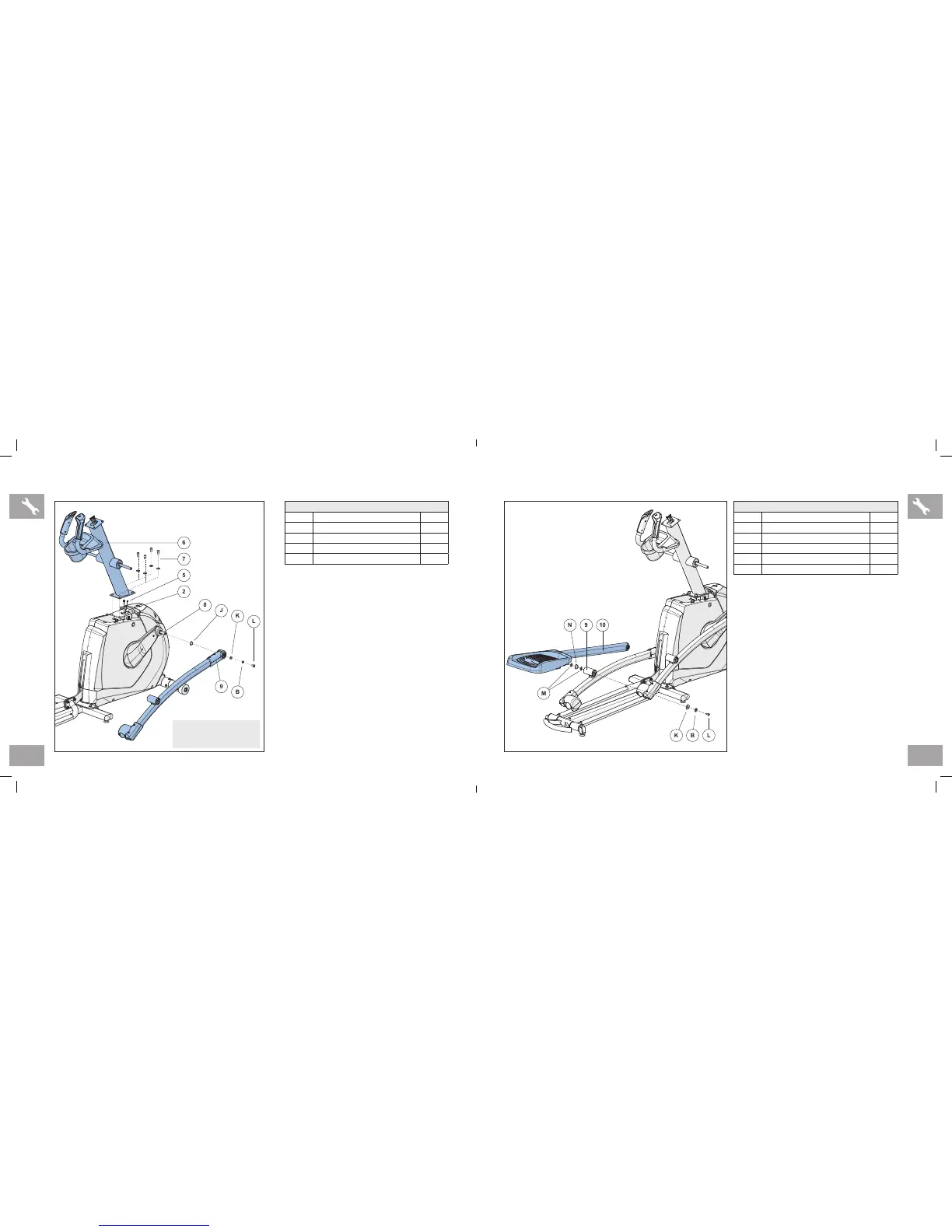
ASSEMBLY STEP 4
A Open HARDWARE FOR STEP 4.
B Carefully pull the CONSOLE CABLE (5)
through the CONSOLE MAST (6) using
the twist tie located inside the CONSOLE
MAST (6).
C Attach CONSOLE MAST (6) to MAIN
FRAME (2) using PRE-INSTALLED
BOLTS AND WASHERS (7).
D Slide WAVY WASHER (J) over CRANK
(8) followed by PEDAL ARM (9) as shown.
Rest pedal arm wheel on guide rail.
E Attach the PEDAL ARM (9) to the CRANK
(8) using 1 FLAT WASHER (K), 1 SPRING
WASHER (B) and 1 BOLT (L).
F Repeat steps D–E on the opposite side of
the elliptical.
HARDWARE FOR STEP 4
PART TYPE QTY
J WAVY WASHER 2
K FL AT WAS H ER 2
B SPRING WASHER 2
L BUTTON HEAD BOLT 2
HARDWARE FOR STEP 5
PART TYPE QTY
M FL AT WAS H ER 4
N WAVY WASHER 2
K FL AT WAS H ER 2
B SPRING WASHER 2
L BUTTON HEAD BOLT 2
ASSEMBLY STEP 5
A Open HARDWARE FOR STEP 5.
B Slide 1 FLAT WASHER (M), 1 WAVY
WASHER (N) and another FLAT
WASHER (M) onto the LOWER LINK
ARM (10).
C Slide the LOWER LINK ARM (10) into the
PEDAL ARM BRACKET (9).
D Attach the LOWER LINK ARM (10) to the
PEDAL ARM (9) using 1 FLAT WASHER
(K), 1 SPRING WASHER (B) and 1
BOLT (L).
E Repeat steps B–D on the opposite side of
the elliptical.
AFG14_3.3AE_5.3AE_7.3AE_OM_r1_4.indd 14-15 5/20/14 9:12 AM