EasyManua.ls Logo

AFi FR-PDA-STO - User Manual

Default Icon
4 pages
Print Icon
To Next Page IconTo Next Page
Loading...
ASSEMBLY INSTRUCTIONS
Before assembling your bed frame, please read through these
ATTENTION! If you receive a damaged or defective item,
please contact afifurnishings at customerservice@afifurnishings.com or 1-800-955-3726
instructions carefully and familiarize yourself with the different parts.
Barrel nut - 2 pcs
Wood dowel 10 X 30mm( 1 1/4") - 4 pcs
JCB M6 X 70mm (2 3/4”) - 2 pcs
Wood screw(1 1/4”) - 14 pcs
Spare - 1 pc
Spare - 1 pc
Spare - 1 pc
BED FRAME
Page 1 of 2
PARTS LIST HARDWARE
A
H
F
I
J
B
C
D
FOOT RAIL
LEFT LEG
RIGHT LEG
SIDE RAILS
SLAT KIT
HB SUPPORT RAIL
FB SUPPORT RAIL
SUPPORT LEGS
1 PC
1 PC
1 PC
2 PCS
2 SET
1 PC
1 PC
3 PCS
1
2
3
4
5
6
7
8
Allen wrench M4 - 1pc
Allen wrench M5 - 1pc
Spare - 1pc
E
JCB M6 X 30mm ( 1 1/8") - 6 pcs
G
JCB M8 X 40mm ( 1 5/8") - 3 pcs
4
4
1
1
D
2
3
B
C
B
C
A
A
B
C
D
A
Attach the legs (2) and (3)
to foot rail (1), using wood dowel
(C) JCB M6 X 70mm (A) and
barrel nut (B).
T
ighten with the Allen wrench (I).
Cover holes with wood button (D) as shown.
NOTE: WE INCLUDE SPARE HARDWARE IN CASE DAMAGE OCCURS DURING ASSEMBLY.
Step 1
Step 2
READY
ASSEMBLE
TO
Adult assembly
JCB M6 X 70mm
Barrel nut
Wood dowel
Wood button
QUEEN
PO:
CODE ITEM
FR-PDA-STO
R-21034X
Spare - 1 pc
Spare - 1 pc
Spare - 1 pc
Wood button - 2 pcs
wood button
Center set of pins.
Attach the side rails (04) to the headboard and footboard (1) using
the bed hook as shown below.
Cap Nut - 6 pcs
Question and Answer IconNeed help?

Do you have a question about the AFi FR-PDA-STO and is the answer not in the manual?

Overview

This document provides assembly instructions for a Queen-sized bed frame and an optional headboard, along with details for attaching the headboard to a metal bed frame. The product is designed for adult assembly and is part of the "Ready to Assemble" furniture line from afifurnishings.com.

Bed Frame Description

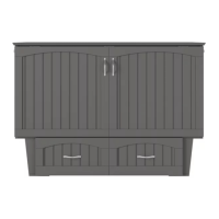
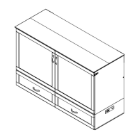
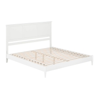
The bed frame is a Queen-sized unit, identified by the item number R-21034X and code FR-PDA-STO. Its primary function is to provide a sturdy support structure for a mattress, consisting of a foot rail, two side rails, a left leg, a right leg, and three support legs. The design incorporates a slat kit for mattress support, along with specific support rails for the headboard (HB) and footboard (FB) sections.

Technical Specifications (Hardware): The assembly requires various types of fasteners and tools:

  • JCB M6 x 70mm (2 3/4"): 2 pieces (plus 1 spare) for connecting legs to the foot rail.
  • Barrel nut: 2 pieces (plus 1 spare) for connecting legs to the foot rail.
  • Wood dowel 10 x 30mm (1 1/4"): 4 pieces (plus 1 spare) for aligning legs with the foot rail.
  • Wood button: 2 pieces (plus 1 spare) for covering screw holes on the foot rail.
  • JCB M6 x 30mm (1 1/8"): 6 pieces (plus 1 spare) for attaching support rails to the slat kit.
  • Cap Nut: 6 pieces (plus 1 spare) for securing support rails to the slat kit.
  • JCB M8 x 40mm (1 5/8"): 3 pieces (plus 1 spare) for attaching support legs to support rails.
  • Wood screw (1 1/4"): 14 pieces (plus 1 spare) for securing the slat kit.
  • Allen wrench M4: 1 piece (plus 1 spare) for tightening M6 fasteners.
  • Allen wrench M5: 1 piece (plus 1 spare) for tightening M8 fasteners.
  • A Phillips head screwdriver (customer supplied) is required for the wood screws.

Usage Features: The bed frame is designed for straightforward assembly, with clear, step-by-step instructions.

  • Step 1: Foot Rail Assembly: Involves attaching the left and right legs (2 and 3) to the foot rail (1) using wood dowels (C), JCB M6 x 70mm screws (A), and barrel nuts (B). The holes are then covered with wood buttons (D) for a clean finish.
  • Step 2: Side Rail Attachment: The side rails (4) are attached to the headboard and footboard (1) using a bed hook mechanism, ensuring a secure connection.
  • Step 3: Support Leg Assembly: Support legs (8) are attached to the HB support rail (6) and FB support rail (7) using JCB M8 x 40mm screws (G) and tightened with an M5 Allen wrench (J).
  • Step 4: Slat Kit and Support Rail Installation: The HB support rail (6) and FB support rail (7) are attached to the slat kit (5) using JCB M6 x 30mm screws (E) and cap nuts (F), tightened with an M4 Allen wrench (I). The slat kit is further secured with wood screws (H) using a Phillips head screwdriver. The instructions also provide guidance for positioning slat supports off-center if a trundle bed is used.

Maintenance Features: The manual emphasizes the importance of periodic maintenance: "We recommend that you periodically recheck that all screws are tight to ensure lasting safety." This suggests that fasteners may loosen over time and should be retightened to maintain the structural integrity and safety of the bed frame. Spare hardware is included to account for potential damage during assembly or for future replacements.

Headboard Description

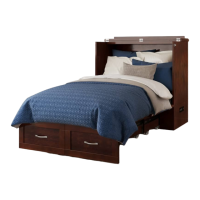
The headboard is an optional component, available in Twin, Full, Queen, and King sizes, identified by codes HB-ORL and item numbers R-28182X (Twin), R-28183X (Full), R-28184X (Queen), and R-28185X (King). Its function is to provide an aesthetic and supportive backrest for the bed.

Technical Specifications (Hardware): The headboard assembly requires:

  • Wooden dowel: 4 pieces (plus 1 spare) for aligning legs with the headboard panel.
  • JCB M6 x 35mm (1 3/8"): 4 pieces (plus 1 spare) for attaching legs to the headboard panel.
  • Allen wrench M4: 1 piece (plus 1 spare) for tightening M6 fasteners.

Usage Features: The headboard assembly is also designed for easy, adult assembly.

  • Step 1: Headboard Leg Attachment: The left leg (2) and right leg (3) are attached to the headboard panel (1) using wooden dowels (A) and JCB M6 x 35mm screws (B). These are tightened with an M4 Allen wrench (F).

Maintenance Features: Similar to the bed frame, the headboard instructions include a general maintenance recommendation: "To ensure lasting safety, we recommend that you periodically check that all screws are tight and all parts are secure."

Attaching Headboard to Metal Bed Frame

This section provides specific instructions for integrating the wood headboard with a separately purchased metal bed frame.

Technical Specifications (Hardware for Metal Bed Frame Attachment): The hardware for this attachment is supplied with the wood headboard, not the metal bed frame.

  • JCB M6 x 25mm (1"): 4 pieces (plus 1 spare) for connecting the headboard to the metal frame.
  • Flat washer: 4 pieces (plus 1 spare) for distributing pressure under the screw head.
  • Split washer: 4 pieces (plus 1 spare) for preventing screws from loosening.
  • Allen wrench M4: 1 piece (plus 1 spare) for tightening M6 fasteners.

Usage Features:

  • Step 1: Headboard-to-Metal Frame Connection: The assembled headboard is attached to the metal bed frame using JCB M6 x 25mm screws (C), flat washers (D), and split washers (E). These are tightened with an M4 Allen wrench (F). The diagram illustrates how the headboard legs align with the metal frame's attachment points.

Maintenance Features: The same maintenance recommendation applies: "To ensure lasting safety, we recommend that you periodically check that all screws are tight and all parts are secure."

Overall, the device manual provides comprehensive instructions for assembling a Queen bed frame and an optional headboard, emphasizing ease of assembly and the importance of periodic maintenance for long-term safety and durability. Spare hardware is consistently included across all components to facilitate assembly and potential future repairs.

AFi FR-PDA-STO Specifications

General IconGeneral
BrandAFi
ModelFR-PDA-STO
CategoryIndoor Furnishing
LanguageEnglish

Related product manuals