5. Conveyor belt, now to be pulled to other end of the bed (A) Fig 14. Rotate belt in direction (B) Fig 14), allowing belt to
removed.
14
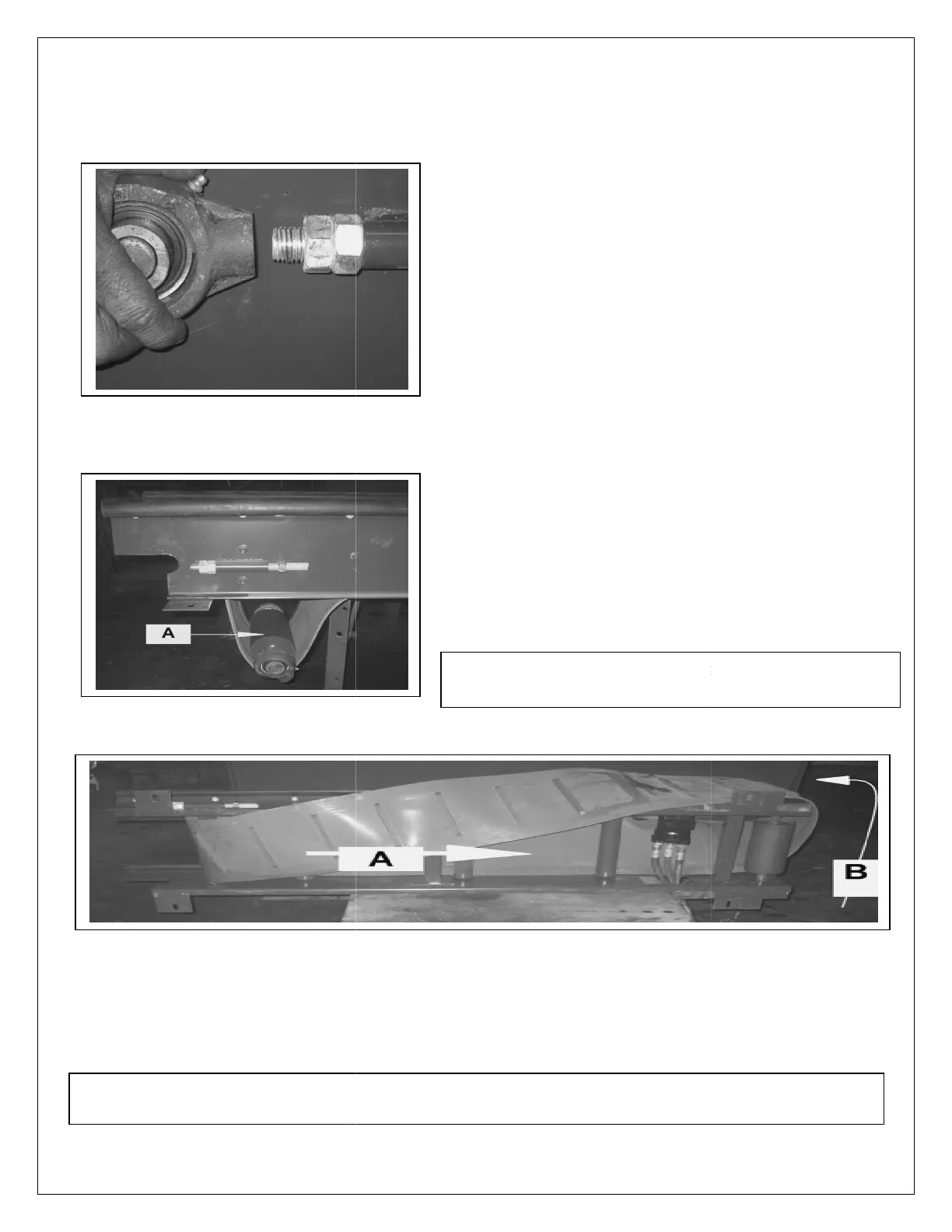
1. Remove the
adjuster threaded bar from the Hanger
bearing. This is easily achieved by locking the two
nuts together, then using the locked nuts to remove
thread from bearing.
2.
Complete this task on both sides of the conveyor.
3.
Fig 13 shows the result. Head roller (A
bearings. It is not required to remove the bearing
from the head roller shaft.
4.
Now remove the assembly (A) from the conveyor.
Removing
assembly (A), may require some gentle
5. Conveyor belt, now to be pulled to other end of the bed (A) Fig 14. Rotate belt in direction (B) Fig 14), allowing belt to
TO BE REPLACED EVERY TWO YEARS
Fig 14
adjuster threaded bar from the Hanger
bearing. This is easily achieved by locking the two
nuts together, then using the locked nuts to remove
Complete this task on both sides of the conveyor.
Fig 13 shows the result. Head roller (A
) c/w two
bearings. It is not required to remove the bearing
Now remove the assembly (A) from the conveyor.
assembly (A), may require some gentle
5. Conveyor belt, now to be pulled to other end of the bed (A) Fig 14. Rotate belt in direction (B) Fig 14), allowing belt to
be
TO BE REPLACED EVERY TWO YEARS
!
 Loading...