14
Schematic Notes:
1. All resistors are in ohms; all capacitors are in microfarads.
2. For components with multiple designations (e.g. R707-710), the lower numbered designation is in the
RLY1 circuit, and the higher numbered designations are in the RLY2, RLY3, and RLY4 circuits
respectively.
3. For IC’s with multiple pin numbers (e.g. 6,4,8,10), the left-most pin number is in the RLY1 circuit, and the
pin numbers to the right are in the RLY2, RLY3, and RLY4 circuits, respectively.
4. The RLY1 and RLY2 circuits use U703; the RLY3 and RLY4 circuits use U704. The left-most pin number
is in the RLY1 and RLY3 circuits.
5. All voltages shown on Figure 7 (Option 750 schematic) are shown with respect to power supply ground.
6. Voltages shown in parenthesis indicate that the value is for the ON or ACTIVE state.
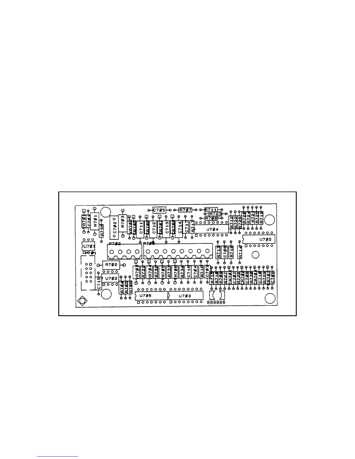
Figure 8. FLT/INH/RLY Component Location
 Loading...