Chapter 2 87
Making Adjustments
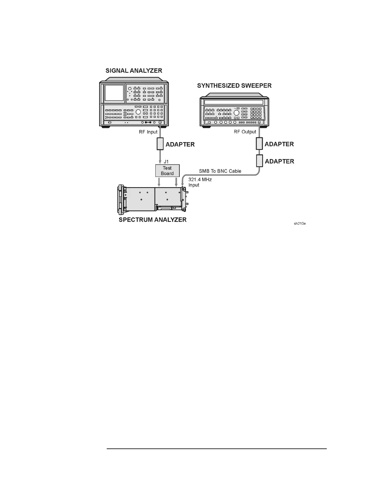
13. Third Converter and Second IF Bandpass
Figure 2-22 Second IF Bandpass Filter Adjustment Setup
8. Press the analyzer
LINE switch to ON.
9. Press the following analyzer keys.
PRESET
SPAN, 0, Hz
10.Connect the microwave spectrum analyzer RF INPUT to J1 of the IF
test board. Refer to Figure 2-22.
11.Adjust A9C44, A9C46, and A9C47 for maximum signal amplitude as
observed on the microwave spectrum analyzer. Adjust the reference
level of the microwave spectrum analyzer, as necessary, to display
the signal below the top graticule.
12.Remove the test board from the A11 slot and install the A11
bandwidth filter assembly.
13.Reconnect W9 to A9J4, 321.4 MHz INPUT.
If you are adjusting an 8590L Option 713, continue with the
“600 MHz Adjustment.”
If you are adjusting an 8591C 8591E, 8593E, 8594E, 8594Q, 8595E,
or 8596E, continue with the “LPF, Attenuator and Adapter Insertion
Loss Characterization.”
 Loading...

