246 Chapter4
Troubleshooting the Analyzer
Using the Internal Service-Diagnostic Routines
Verify the 10 V reference detector
This service-diagnostic routine verifies the 10 V reference. +10 V is
used as a reference for the DACs and originates on the A7 analog
interface board assembly. Frequency and amplitude errors will occur if
this voltage is incorrect.
1. Return to the diagnostics menu by pressing the following analyzer
keys.
CAL, More 1 of 4, More 2 of 4
SERV DIAG, More 1, More 2, More 3
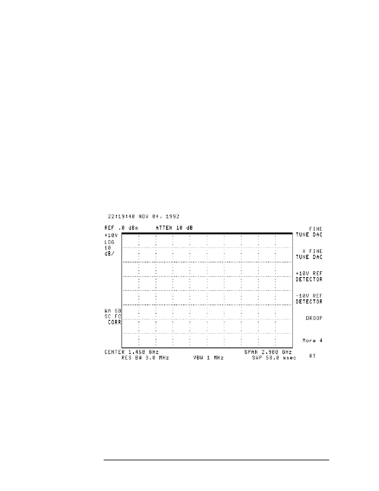
2. Verify the 10 V reference detector by pressing 10V REF DETECTOR.
• If the signal trace is at the top of the display, the 10 V reference
detector is functioning properly. See Figure 4-13.
• If the signal is not at the top of the display, the problem is isolated
to the A7 analog interface board assembly. Refer to Chapter 6 for
further troubleshooting.
Figure 4-13 10 V Reference Detector
 Loading...

