286 Chapter6
Troubleshooting the RF Section
6a. 8590L, 8591C, and 8591E
To check control of the A3 input attenuator
The A7 analog interface assembly controls the three attenuator steps in the A3
input attenuator. Each attenuator step requires one control line, as shown in
Table 6-3. The W13 wire harness connects the attenuator to A7J2 on the A7
assembly. W13 also supplies the +15 V power supply for the attenuator. Locate
W13 using the top view of the analyzer in Chapter 11, “Major Assembly and
Cable Locations.”
Use a digital multimeter (DMM) and the values from Table 6-3 to check the
control voltages for each attenuator step. Refer to Figure 6-1 for the location of
the connector pins on A7J2. Measure the voltages at the A7J2 pins on the trace
side of the A7 assembly.
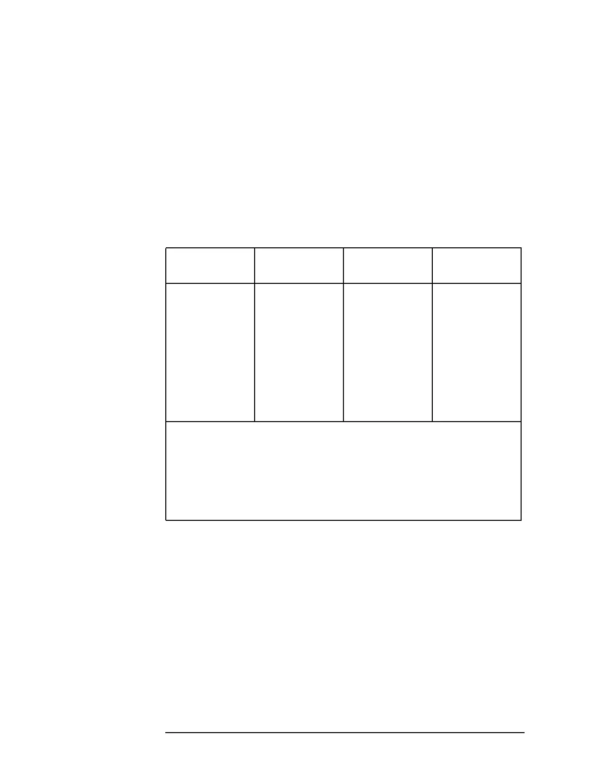
Table 6-3 Input Attenuator Control Output at A7J2
Attenuator
Setting (dB)
10 dB Step (A7J2
Pin 6)
20 dB Step (A7J2
Pin 5)
30 dB Step (A7J2
Pin 8)
0LLL
10 H L L
20 L H L
30 H H L
40 H L H
50 L H H
60HHH
H = +15 V (A high output indicates that the attenuator
step is in the signal path.)
L = +0.8 V
These control voltages are valid only if the
A3 Input Attenuator is connected to A7J2.
 Loading...

