Appendix Service Information
Measurement Techniques
182
General Measurement Techniques
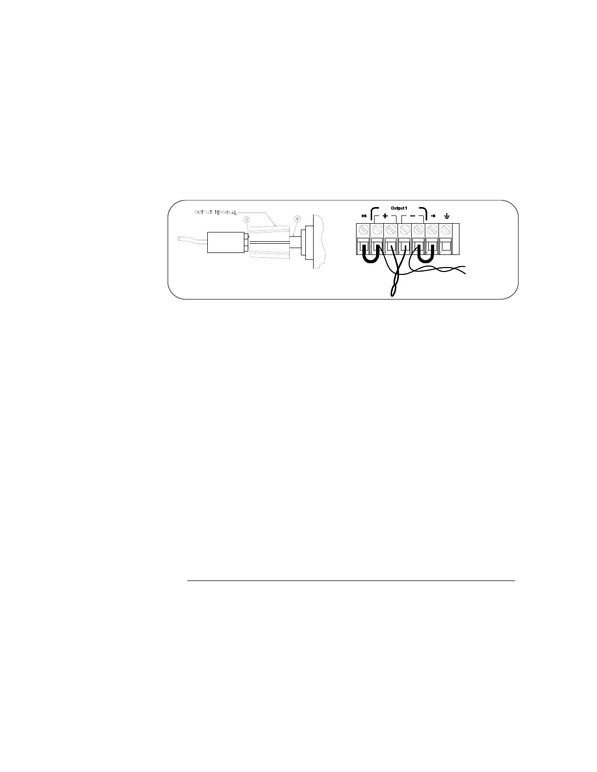
To achieve best results when measuring load regulation, peak to peak voltage, and
transient response time of the power supply, measuring devices must be connected
through the hole in the neck of the binding post at (A) while the load resistor is plugged
into the front of the output terminals at (B). A measurement made across the load
includes the impedance of the leads to the load. The impedance of the load leads can
easily be several orders of the magnitude greater than the power supply impedance
and thus invalidate the measurement. To avoid mutual coupling effects, each
measuring device must be connected directly to the output terminals by separate pairs
of leads.
Figure A-2 Front/Rear Panel Terminal Connections
Electronic Load
Many of the test procedures require the use of a variable load resistor capable of
dissipating the required power. Using a variable load resistor requires that switches
should be used to connect, disconnect, and short the load resistor. An electronic load,
if available, can be used in place of a variable load resistor and switches. The electronic
load is considerably easier to use than load resistors. It eliminates the need for
connecting resistors or rheostats in parallel to handle power, it is much more stable
than carbon-pile load, and it makes easy work of switching between load conditions
as is required for the load regulation and load response tests. Substitution of the
electronic load requires minor changes to the test procedures in this chapter.
Programming
Most performance tests can be performed from the front panel. However, an GPIB or
RS-232 controller is required to perform the voltage and current programming
accuracy and readback accuracy tests.
The test procedures are written assuming that you know how to program the power
supply either from the front panel or from an GPIB or RS-232 controller. See “Output
Setting and Operation Commands”, starting on page 85 for complete instructions on
remote programming.
TO MONITORING
DEVICE
TO LOAD OR
CURRENT
RESISTOR
[Front Panel (Side View)]
(Rear Panel)
 Loading...


