12
Block diagram
Since Option UN7 cannot demodulate
RF, loopback measurements are not
supported. For GSM loopback BER
testing, please consult the informa-
tion for Option 300, a BER extension
for GSM base station receiver test.
Note the signal generator must have
an internal I/Q baseband generator
(Option UN8) installed to support
the BER analysis option.
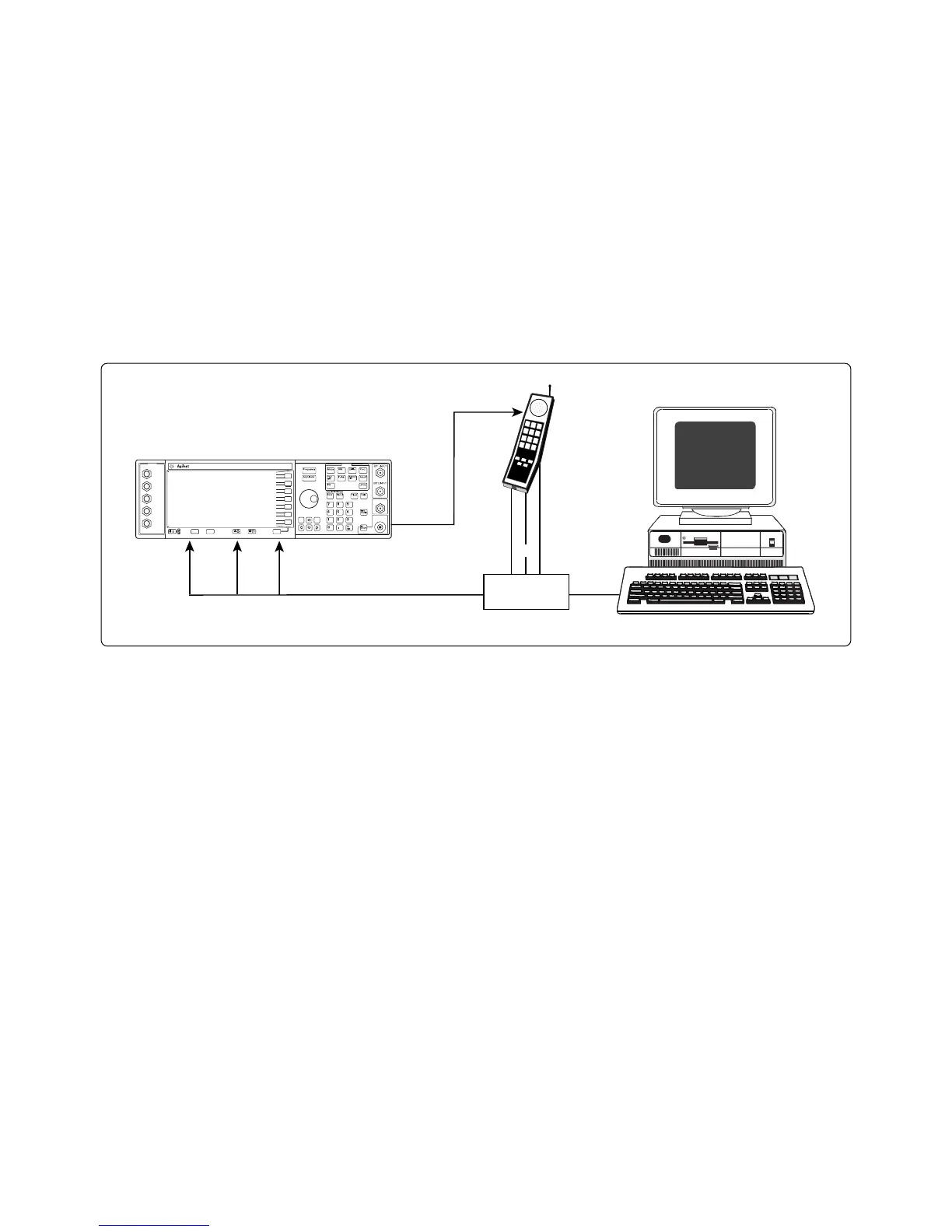
Two input signals are required
for BER measurements:
• Data: the demodulated PN9 or
PN15 bit stream from the device
under test.
• Clock: used to clock in data at the
appropriate rate.
The clock gate is needed for bursted
data or when analyzing demodulated
framed (data and control) bit
sequences.
A user-supplied interface box is
also required when the device under
test does not output the correct TTL
signal levels or to generate synchro-
nized data and clock signals for
framed transmissions.
Data
Clock
Gate
Clock
Gate
Data
RF
Interface
box
INPUT
I
Q
DATA
DATA
CLOCK
SYMBOL
SYNC
Preset
Local
More
More
Inc.
Set
MenusE4433B 250 kHz to 4.0 GHz
ESG-D SERIES DIGITAL SIGNAL GENERATOR
LF OUTPUT
RF OUTPUT
50Ω
Common setup for bit-error-rate measurement of mobile phones.
 Loading...


