EasyManuals Logo

Agilent Technologies E4443A Installation Guide

Agilent Technologies E4443A
40 pages
To Next Page IconTo Next Page
To Previous Page IconTo Previous Page
Page #15 background imageLoading...
Page #15 background image
Installation Guide 7
E444xAU IF Output Options E444xAU Options H20, H25 and H70
Installation Procedure
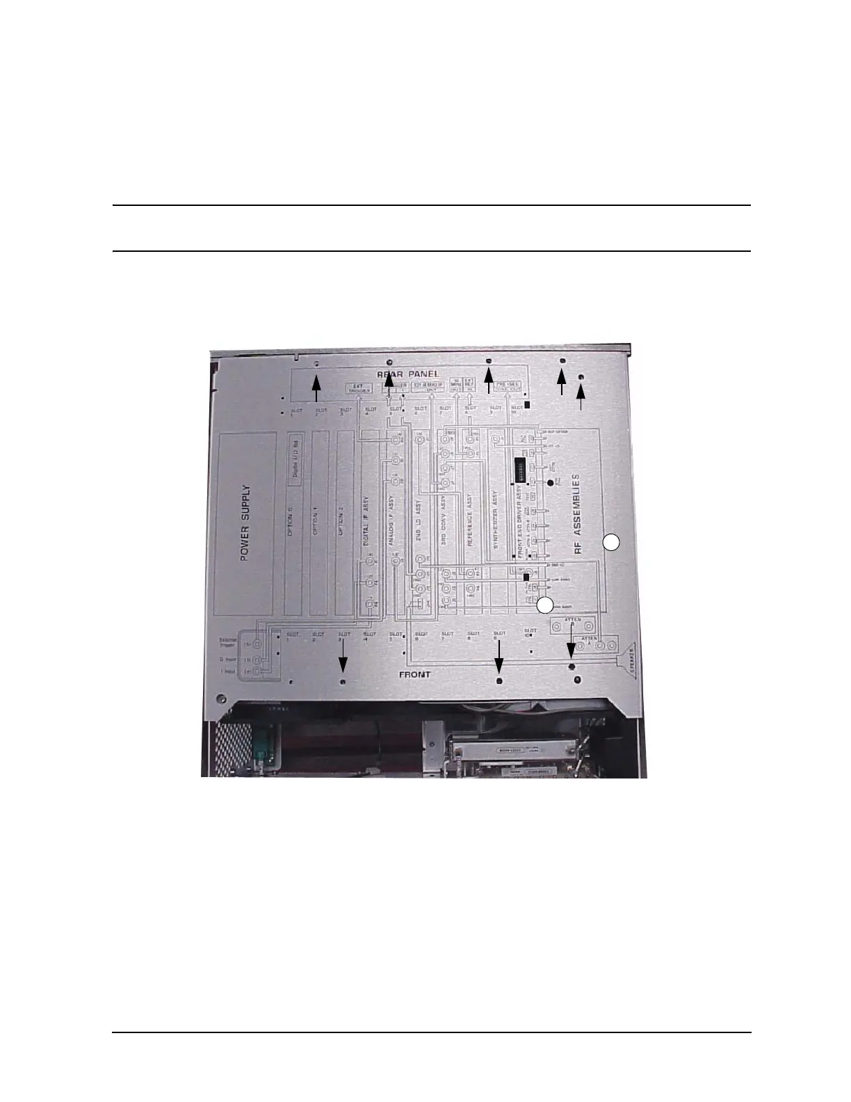
5. Remove the chassis cover, using a #10 Torx driver. Refer to Figure 4 for location of top
screws. There are ten screws to remove from the “speaker” side of the chassis cover and
two screws from the “power supply” side of the chassis cover. Place all hardware in a
safe location for re-installation.
NOTE The E4446A and E4468A have two additional screws in the chassis cover. The
white circles indicate the approximate position.
Figure 4 Chassis Cover Screw Location

Other manuals for Agilent Technologies E4443A

Questions and Answers:

Question and Answer IconNeed help?

Do you have a question about the Agilent Technologies E4443A and is the answer not in the manual?

Agilent Technologies E4443A Specifications

General IconGeneral
BrandAgilent Technologies
ModelE4443A
CategoryMeasuring Instruments
LanguageEnglish

Related product manuals