Installation Note E8364-90024 13
Step 5. Replace the A23 Channel R1 Detector
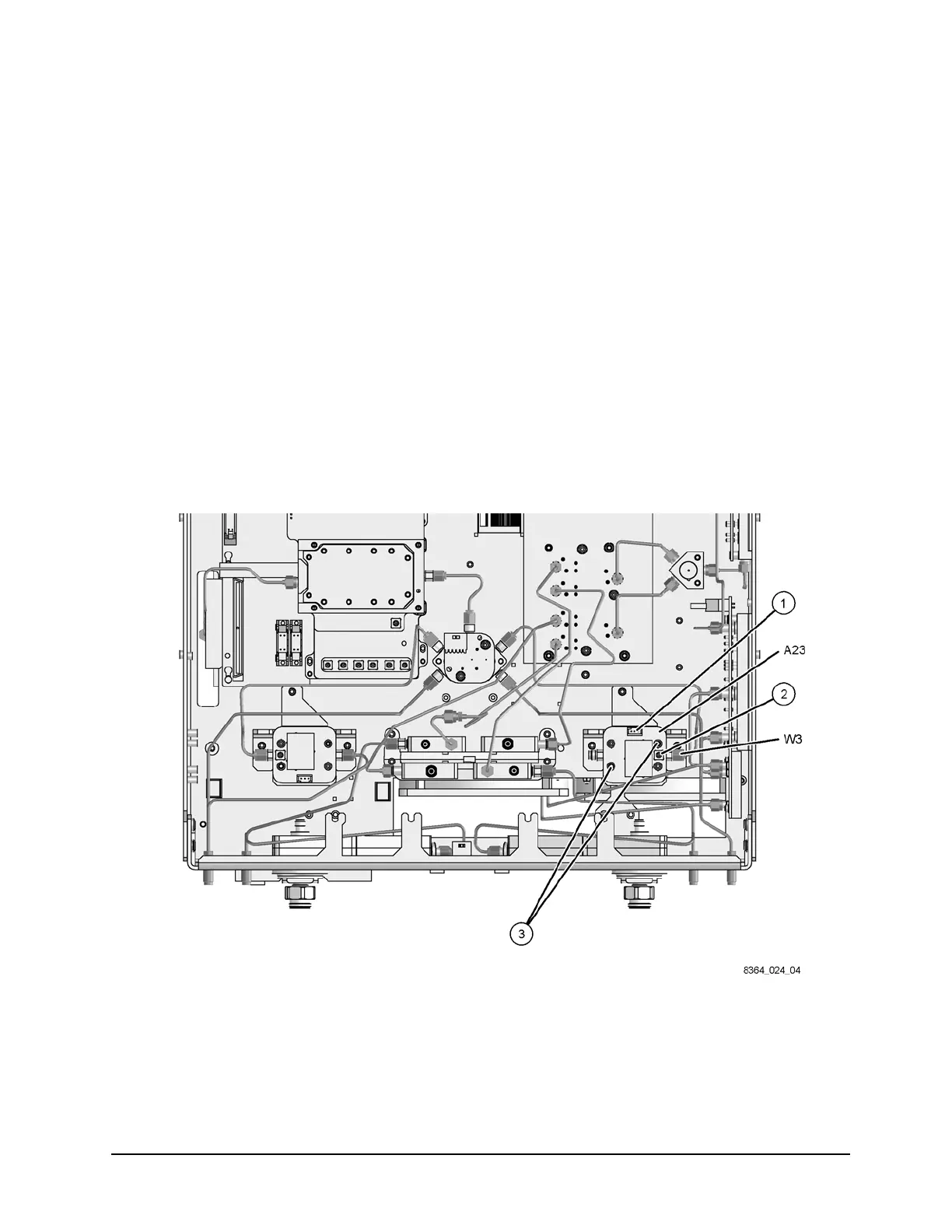
Refer to Figure 8 for this the procedure. The new parts referenced in this procedure are listed
in Table 1 on page 4.
1. Using a 5/16-inch wrench, disconnect cable W3 from the A23 channel R1 detector.
2. Disconnect the stranded control cable (item
①) and the flexible RF cable (item ②) from the
detector.
3. With a T-10 TORX driver, remove the two mounting screws (item
③) and remove the
detector from the analyzer.
4. Place the new detector (provided) into position. With a T-10 TORX driver, install the two
mounting screws (item
③) to secure the detector.
5. Using a 5/16-inch torque wrench, connect cable W3 to the new detector.
6. Reconnect the stranded control cable (item
①) and the flexible RF cable (item ②) to the
new detector.
Figure 8 Channel R1 Detector Replacement
 Loading...


