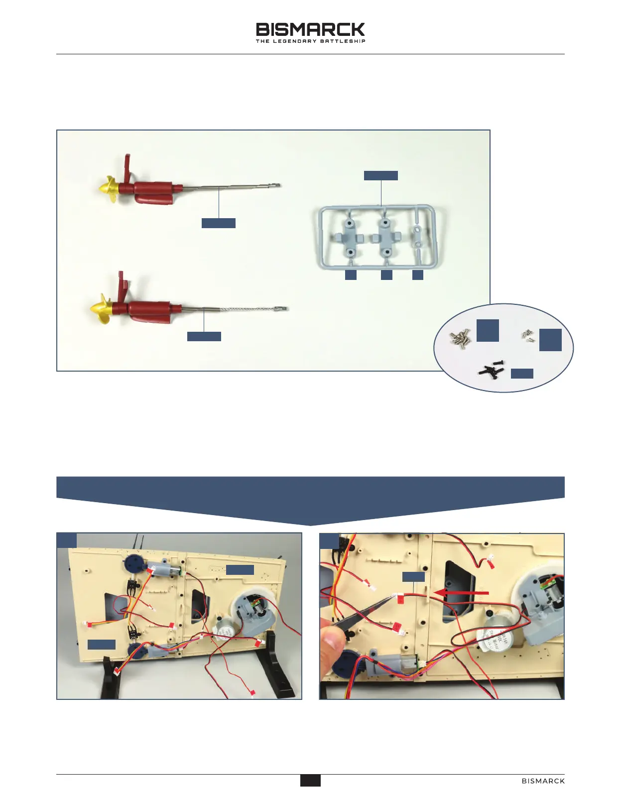
01. ARRANGE AND CONNECT THE CABLES
01
02
12001
PM
2 x 4
PM
2 x 3
12002
12003
CA B
PB
9901
6401
C5
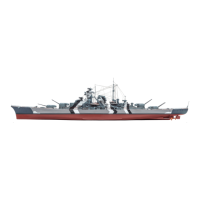
STAGE 120
THE TWO OUTER PROPELLERS
COMPONENTS CHECKLIST
120-01: Port propeller with bracket, shaft,
support and sleeve
120-02: Starboard propeller with bracket,
shaft, support and sleeve
120-03: Two brackets and a shaft grip
Run the cable labelled C-5 from the 38cm turret
motor through the bracket in the centre of the upper
deck structure, as indicated by the arrow.
Carefully place the aft superstructure section (sections
64-01 and 99-01) in support brackets so that you can
access the underside of the upper deck. Take care not
to damage any of the parts already in place.
PM: Nine 2 x 4mm PM screws
PM: Three 2 x 3mm PM
screws
PB: Five 2 x 6mm PB screws
NOTE: In this stage we
only use the 2 x 6mm PB
screws. The other parts
will be fitted in the next
stage.
10
10
AGORAMODELS BISMARCK
PB
AGORAMODELS BISMARCK