6401
6401
11901
11901
C6, C7,
C8, C9
C1
C3
C2
C10
C8
C9
C5, C6,
C7
PB
07 08
05 06
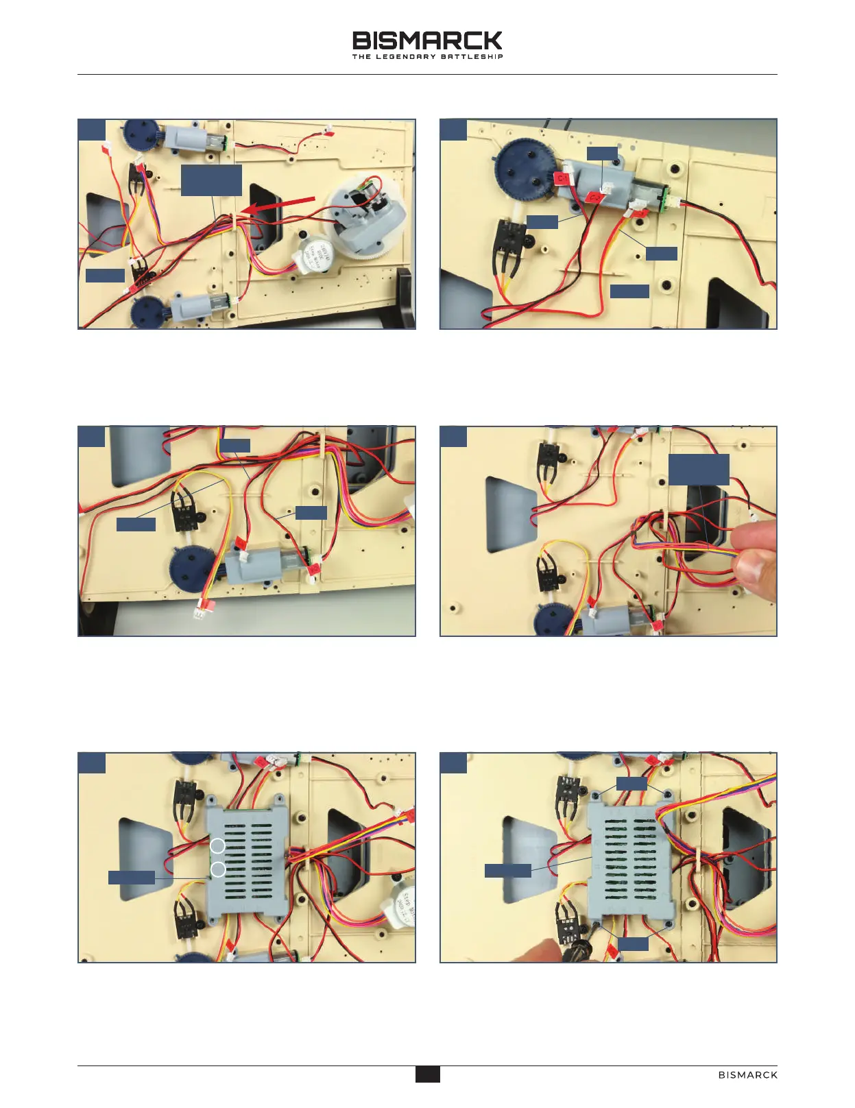
Run the cables labelled C-6, C-7, C-8 and C-9
through the same bracket on the upper deck section
64-01, in the same direction as C-5, as shown.
Press the cables labelled C-1, C-2 and C-3 into the
slots in the rib on the underside of deck section
64-01, as shown. The slot on the right in this photo
remains empty.
Press the cables labelled C-8, C-9 and C-10 into the
three slots in the bar on the other side of the deck,
as shown.
Gather together the cables marked C-5, C-6 and
C-7 and run them towards the rear of the deck (to
the right in this photo) so that the connectors are
clear of where the circuit board 119-01 will be
attached (see next two steps).
Take the circuit board 119-01 and position it on the
upper deck in the orientation shown. Ports 11 and 12
are on the left in this photo (circled in white).
Fix the circuit board 119-01 in place using four
2 x 6mm PB screws.
03 04
PB
11
11
AGORAMODELS BISMARCK
12
AGORAMODELS BISMARCK